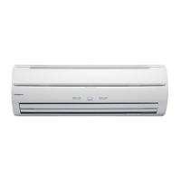
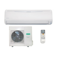
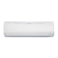
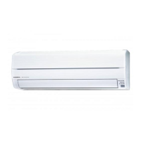
Do you have a question about the General ASHA12LCC and is the answer not in the manual?
Details the model type, cooling, and heating capacities of the unit.
Provides the physical measurements for the indoor and outdoor units.
Lists the gross and net weight for both indoor and outdoor units.
Covers power source, frequency, running current, and input watts.
Specifies sound pressure levels for indoor and outdoor units in different modes.
Details refrigerant type, pipe length, and charge amount.
Describes the compressor type, discrimination, and refrigerant used.
Provides fan motor power source and speed specifications.
Electrical circuit diagram for the indoor unit components.
Electrical circuit diagram for the outdoor unit components.
Details jumper settings for custom code and auto restart functions.
Diagram of the outdoor unit inverter assembly and its connections.
Diagram of the outdoor unit controller PCB assembly.
Errors related to serial communication signals between units.
Faults detected in indoor unit thermistors (open/short).
Faults detected in outdoor unit thermistors (open/short).
Control errors within the indoor unit, including relay and power issues.
Control errors in the outdoor unit, like CT abnormal or fan drive issues.
Errors related to the indoor unit fan motor operation.
Errors indicating issues with the refrigerant system.
Errors related to optional functions or specific circuit faults.
Errors indicating a mismatch or fault in the unit's model identification.
List of part numbers and descriptions for indoor unit components.
List of part numbers and descriptions for outdoor unit components.
| Brand | General |
|---|---|
| Model | ASHA12LCC |
| Category | Air Conditioner |
| Language | English |


 Loading...