Installing your thermostat
6. System function settings
With power off, press and hold both M and for 5
seconds to enter the System Functions. Press M to
scroll through the available functions, and use the
and arrows to change the available options.
Your thermostat will automatically exit the System
Functions settings after approximately 15 - 20
seconds of inactivity. All settings are automatically
Wiring your thermostat
Wiring your thermostat
Please note:
1.“Err” on your thermostat indicates a fault without the external (floor) sensor.
Your thermostat will be inoperative until the error is rectified.
2. When sensor selection is “AL” (option 3 above) the room temperature will
be displayed on your thermostat by default. The floor temperature can be
displayed temporarily by pressing the button for three seconds. Your
thermostat will revert to display the room temperature after several seconds.
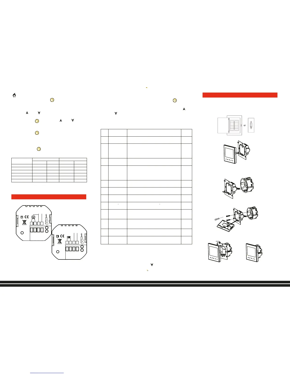
Your thermostat is suitable for installation within
a standard 86mm pattress box or European 60mm
round pattress box.
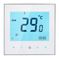
will show in the bottom left of the screen.
Touch and hold the icon until the weekday
schedule settings appear (1 2 3 4 5 will show
along the top of the screen).
Use the and arrows to adjust the time for
the 1st (Comfort) period
Press the icon and use the and arrows
to set the temperature for the 1st period.
Repeat this process for periods 2 – 6.
Press the icon once more to enter the
weekend schedule settings (6 & 7 will show along
the top of the screen).
Repeat the above process to set the weekend
schedule. Press once more to confirm and exit.
Default settings for program schedule
Time display
Default settings above assume a 5+2 (day) weekly
program.
Please note:
Do not over-tighten the terminals in your thermostat
as damage may occur.
Code Function Setting & options Default
1
Air temperature
calibration
Range is -9°C to +9°C for internal sensor -2
2
Switching
differential
The number of degrees above/below set temperature before
switching on/off
When default is set to 1°C the thermostat will switch on 0.5°C
below the set temperature and will switch off 0.5°C above the
1
3 Button locking
00: = All buttons will lock except the Power button
01: = All buttons will lock
01
4 Sensor selection
In = control temperature using the internal sensor
Ou = control temperature using the external (floor) sensor
Al = control temperature using internal sensor to control
temperature, and external sensor to limit the floor temperature
Remark: Please make sure the right sensor. If choose the
wrong or bad one, LCD will display Err.
In for GA
Al for GB
5
Minimum
temperature setting
Range is 5°C - 15°C.
5
6
Maximum
temperature setting
Range is 15°C - 45°C.
35
7 12/24 hour clock
00: 12h: = 12 Hour clock
01: 24h: = 24 hour clock
01
8
Display Mode
00:display both set temp. and room temp.
01:display set temp. only
00
9
Minimum floor
temperature
protection setting
When chosen floor temperature is reached, the system will
automatically switch off. This facility is used to protect delicate
0
A
Maximum floor
temperature
protection setting
When chosen floor temperature is reached, the system will
automatically switch off. This facility is used to protect delicate
26
B Backlight On Time 3-99S. 10
C
setting
00: Normal Status 01:Return to factory setting
00
1
5
AC95~230V
IP20
N
L
1
2
3
4
M
Close Open
5
6
NTC
GA
L1
N1
LOAD
IP20
N
L
1
2
3
4
NTC
5
6
GB
AC95~230V
GA for water heating and GB for electric heating;
External Sensor is optional.
The electrical connections can be made only by a certified
electrician.
Step 1. Keep power off. See Fig 1.
Fig 1
Step 2. Remove the mounting Plate. See Fig 2.
Fig 2
Step 3. Connect power supply, load and external (floor) sensor
into the appropriate terminals if there is external sensor.
(see “Wiring your thermostat” for details and Fig 3).
Fig 3
Step 4. Fix the mounting plate into the wall with screws in
the box. See Fig 4
Fig 4
Step 5. Fasten body of thermostat and the mounting plate
through the groove. See Fig 5.
Fig 5
Step 6. Installation complete. See Fig 6.
Fig 6
RISK OF ELECTRICAL SHOCK.
Disconnect/isolate
power supply prior to making electrical connections.
Contact with high voltage components can cause electrical
shock, severe injury or death.
Orgovánová 2 917 02 Trnava www.eco-term.net
Eco-Term sp. z o.o. ul. Mały Płaszów 10 30-720 Kraków www.eco-term.eu
Eco-Term Group s.r.o Orgovánová 2 917 02 Trnava www.eco-term.net
made in China
 Loading...