9
English
OPERATION
WARNING:
To reduce the risk of serious personal injuries, read and follow all
important safety warning and instructions before using this tool.
WARNING: Always be sure that the tool is switched
off before insertion or removal of the battery pack.
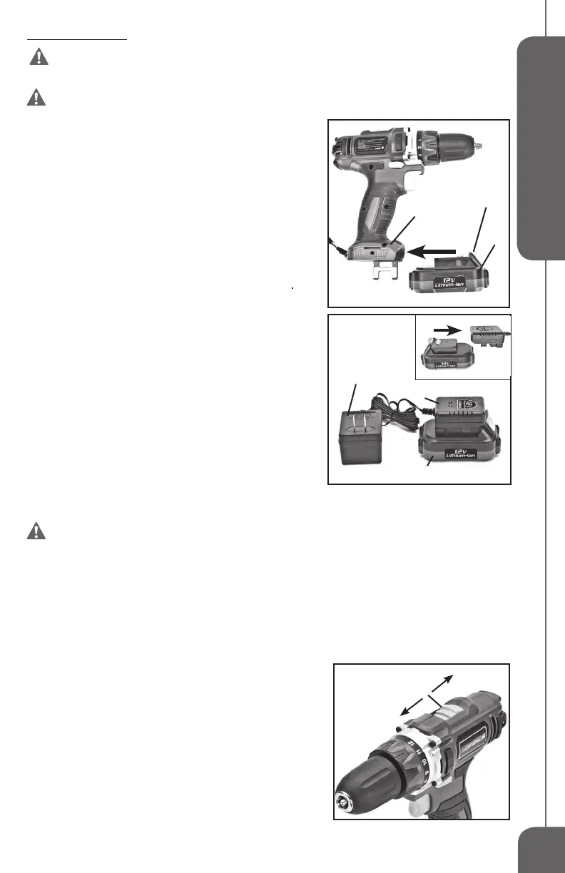
INSTALLING OR REMOVING THE BATTERY
PACK (FIG 2)
• To install the battery pack, slide the battery pack (1) into the
bottom of the tool housing (2) all the way until it locks in place
with a click, as shown in FIG 2. Lightly pull on the battery to
ensure it is locked into place and will not accidentally fall out of
the tool, causing an injury.
• To remove the battery pack, pull the battery pack away from the
tool while depressing the locking tab (3).
CHARGING THE BATTERY (FIG 3)
NOTE:
Always Check that the power supply corresponds to the
voltage on the ratings plate.
• Plug the charger adaptor (1) into a 120 Volt AC Power Source.
The green light on the charger stand (3) will illuminate, indicating
the charger is powered.
• Slide the battery (2) all the way into the charger stand (3) until
it locks in place with a click, as shown in FIG 3. The red light on
the charger stand will illuminate, indicating that the battery is
charging.
• The red light will go off after charging is complete.
• Batteries may become warm while charging. This is normal.
• If battery is hot after continuous use in the tool, allow it to cool
down to room temperature before charging. This will extend the
life of your batteries.
NOTE: It takes approximately 3-5 hours to charge up a completely discharged battery.
WARNING: Always disconnect the battery pack from the tool or place the switch
in the locked or off position before any assembly, adjustments or changing accessories.
TRIGGER SWITCH ACTION
• Turn the drill on by depressing the trigger switch (4-FIG 1).
• Depressing the switch further will produce more speed and torque.
• Use the Reversing Switch (5-FIG 1) to change the direction of rotation of the drill.
• The Reversing Switch has three positions: Forward, Reverse, and Off (middle).
• Always check the rotation before beginning your work.
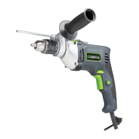
TWO-SPEED GEAR SWITCH (FIG 4)
• Slide the speed gear switch (A) to choose between position 1
for low speed range (0-350 RPM) and position 2 for high speed
range (0-1,300 RPM).
• The low speed range has more power and torque. Use the low
speed range for high power and torque applications.
• The high speed range is for fast drilling or driving applications.
LED WORK LIGHT
Your tool has a built-in LED work light (6-FIG 1) to illuminate
the work area. When you turn on the tool, the work light will
automatically turn on.
FIG 2
1
2
3
A
2
1
FIG 4
FIG 3
1
3
2
2
3