Do you have a question about the Genesys GDR- NAV Series and is the answer not in the manual?
Provides a description of the Genesys Aerosystems (Genesys) Digital Radio (GDR) series installation in an aircraft.
This manual includes installation and checkout procedures for the GDR.
Stylistic elements used throughout this manual are listed in Table 1.
Discusses warnings and responsibilities for equipment modification and licensing.
Instructions for unpacking and identifying GDR components, handling damaged items.
Lists special tools required for installation, meeting MIL specification M22520.
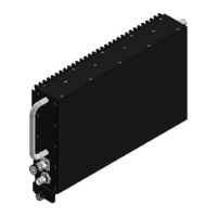
Describes the GDR as a remotely mounted receiver/transmitter with various functions.
Details specifications and major components of the GDR system.
Lists electrical specifications, including power inputs, antenna specs, and audio outputs.
Outlines environmental testing requirements from DO-160F for the GDR-XXXX.
Lists the TSO applicability for the GDR-XXXX system.
Lists TSO deviations granted for the GDR-XXXX.
Defines acronyms and abbreviations used throughout the document.
States notes and warnings regarding airworthiness limitations for the GDR.
Provides guidance on following avionics practices and performing electrical load analysis.
Details general procedures and methods for terminating cable shields.
Provides guidelines for locating and mounting the tray assembly in the aircraft.
Discusses COM, NAV, and MB antenna placement and requirements.
Explains the use of signals for avionics and audio panel interface, including power and data buses.
Presents mechanical drawings of the GDR-XXXX unit.
Illustrates pin configurations for P1 and P2 connectors.
States the purpose of the ground functional tests for proper GDR installation.
Lists the necessary test equipment for GDR functionality checks.
Details pre-operational checks including structural tests and resistance verification.
Outlines operational and continued airworthiness tests for the GDR.
Lists the tools required for troubleshooting the GDR system.
Provides setup instructions for troubleshooting procedures.
Describes how to interpret fault indications for troubleshooting.
Provides a table to assist in troubleshooting GDR and sensor failures.
Details ARINC labels 030 and 047 for VHF COM frequency and bandwidth.
Explains ARINC label 034 for VOR/ILS frequency selection and status.
Describes ARINC label 035 for DME frequency tuning and navigation source.
Details ARINC label 040 for UHF COM transceiver control and modulation.
Explains ARINC label 173 for Localizer deviation transmission.
Describes ARINC label 174 for Glideslope deviation transmission.
Details ARINC label 222 for VOR bearing and marker beacon tones.
Explains ARINC labels 242 and 244 for VOR Ground Station ID Morse code.
Details ARINC labels 263 and 264 for ILS Ground Station ID Morse code.
Describes ARINC label 350 for LRU maintenance status and BIT.
Lists ARINC 429 update rates for various labels.