13
ENGLISH
EULAVYALPSID SUTATSETAG
tsertaetaG
gninepoetaG
)hpargaraptxenees-delbaneerusolc-ercitamotuahtiwylnO(sutat
sesuapninepoetaG
gnisolcetaG
Fig. 4
SDELNOFFO
MILAremrofsnartladiorotybylppusrewoP deilppusrewoponroseirettabybdeilppusrewoP
1CCF deppirttonhcti
ws-timilgnisolc1rotoM deppirthctiws-timilgnisolc1rotoM
1ACFdeppirttonhctiws-timilgninepo1rotoM deppirthct
iws-timilgninepo1rotoM
2CCF deppirttonhctiws-timilgnisolc2rotoM deppirthctiws-timilgnisolc2rotoM
2ACFdeppi
rttonhctiws-timilgninepo1rotoM deppirthctiws-timilgninepo2rotoM
POTSdetavitcatondnammocpotS detavitcadnam
mocpotS
LC-WSFdeppirttonecivedytefasgnisolC deppirtecivedytefasgnisolC
PO-WSFdeppirttonecivedytefasgninepO
deppirtecivedytefasgninepO
7. CONTROL LEDS
N.B.:
• Indicated in bold: status of LEDs with gate closed, control unit powered, and both limit-switches installed.
• If the limit-switches are not used, the relevant contacts must be jumper connected and LEDs FCC1 - FCA1 - FCC2 - FCA2 must be
lighted.
• If no STOP devices are connected, jumper connect the input. The STOP LED must be lighted.
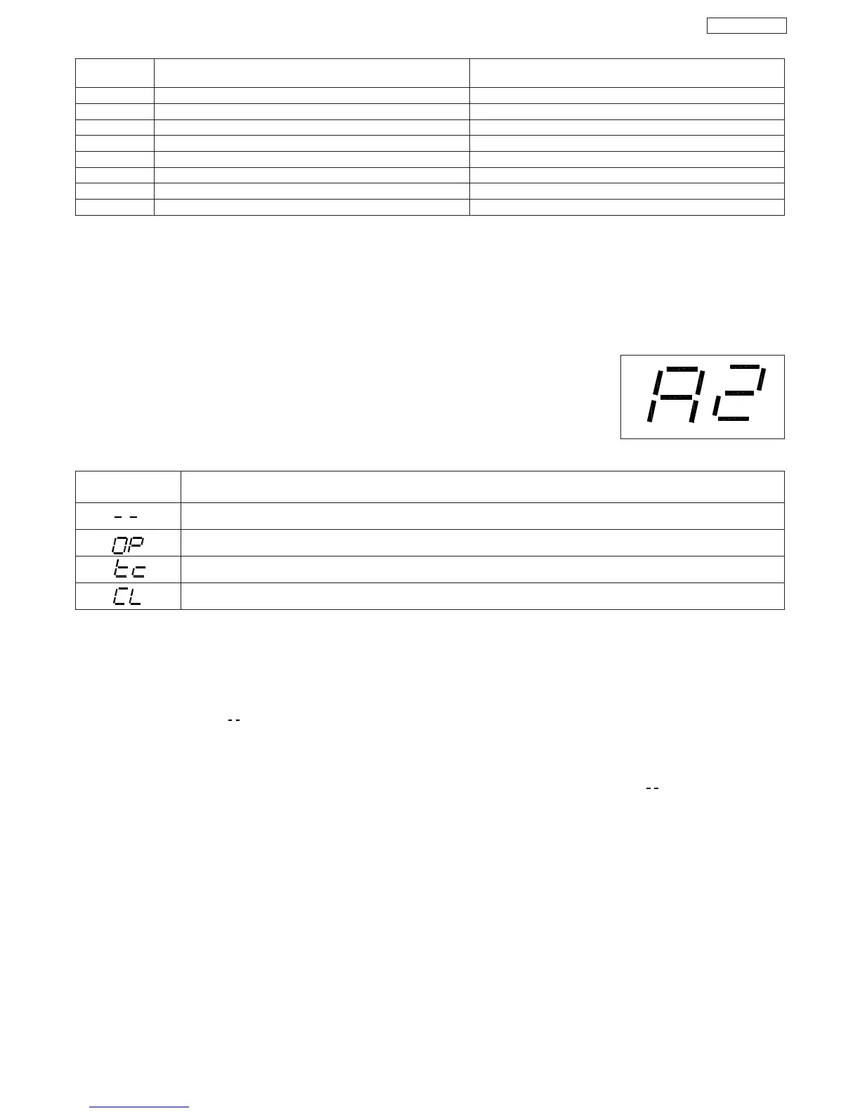
8. OPERATION OF DISPLAY
The control unit has a handy display for viewing and programming the operating parameters. Furthermore, it constantly shows gate status
during normal operation.
When operating parameters are being displayed and programmed, the display shows the selected
parameter on the left, and its set value on the right. Fig. 04 shows the viewing example of parameter “A”
at value “2”.
During normal operation, the display shows gate status. The displayed values are indicated on the following
table:
9. ADJUSTING THE OPERATING PARAMETERS
N.B.: Before you begin adjusting the operating parameters, select the type of operation for the control unit: with or without encoder (see
paragraph 6).
To access operating parameter adjustment, follow the instructions below:
1- When you have made all the necessary connections, power up the system and check if all the signalling LEDs are in the situation
specified in paragraph 7.
2- The display shows value “ ”.
3- Press and hold down push-button P2 until the display shows the name and value of the first parameter.
4- Press push-button P1 to change the value of the parameter.
5- To move on to the next parameter, press push-button P2.
6- When 60 seconds have elapsed without any key being touched, the control unit exits the adjustment mode. You can manually exit
the adjustment mode by scrolling all the parameters with push-button P2. When the display shows value “ “, you have returned to
normal operation.
 Loading...