Do you have a question about the Genius G1100 and is the answer not in the manual?
Charger is not charging, energy save is active. An orange LED illuminates when selected.
For 12V Wet Cell, Gel Cell, EF, MF, CA batteries. A white LED illuminates when selected.
For 12V batteries below 50°F or AGM batteries. A blue LED illuminates when selected.
For 6V Wet Cell, Gel Cell, EF, MF, CA batteries. A white LED illuminates when selected.
For 12V lithium-ion batteries including LiFePO4. A blue LED illuminates when selected.
Connect the red battery clamp or eyelet to the positive terminal (POS,P,+).
Connect the black battery clamp or eyelet to the negative terminal (NEG,N,-) or vehicle chassis.
Plug the charger's AC power plug into a suitable electrical outlet after other connections are made.
Disconnect in reverse sequence, negative first (or positive first for positive ground systems).
Indicates battery is <25% charged (pulsing) or 25% charged (solid red).
Indicates battery is <50% charged (pulsing) or 50% charged (solid red).
Indicates battery is <75% charged (pulsing) or 75% charged (solid orange).
Indicates battery is <100% charged (pulsing) or fully charged (solid green).
Indicates battery is in maintenance mode, fully charged and topped off.
Battery will not hold a charge. Have battery checked by a professional.
Possible battery short. Have battery checked by a professional.
Battery voltage too high for selected charge mode. Check battery and mode.
Reverse polarity. Reverse the battery connections.
Battery voltage too low. Jumpstart battery to raise voltage.
Returns to the last selected mode when the charger is restarted.
Alters the charging process based on organic battery feedback.
Applies high-voltage pulse charge for low-voltage, sulfation, or lost capacity.
Protects against reverse polarity, sparks, overcharging, and overheating.
Charges two times faster than traditional battery chargers.
Adjusts for varying AC line voltage for consistent charging.
Resistant to dirt, water, UV, impact, and crush.
High-frequency energy conversion for ultra-compact, lightweight charger.
Counteracts increased cyclic energy demands in micro-hybrid vehicles.
Multi-level safety barrier preventing abnormal and unsafe conditions.
Stabilizes internal battery chemistry for increased performance and longevity.
Keeps battery fully charged without overcharging, safe for indefinite connection.
Minimizes energy consumption when full power is not needed.
Charge LEDs dynamically track battery state-of-charge against load current.
Visual diagnostic tool for detecting reverse polarity, low-voltage, or damaged batteries.
Automatically enables charging port to charge CANBUS systems.
Internal temperature sensors adjust charge based on ambient climate.
Checks battery's initial condition (voltage, SOC, health) to determine stability before charging.
Initializes desulfation process for discharged/sulfated batteries by pulsing small currents.
Starts the charging process with a gentle (soft) charge.
Begins bulk charging, returning 80% of the battery's capacity.
Brings charge level to 90% by delivering small currents; limits gassing, prolongs life.
Finalizes charging to maximum capacity, recaptures capacity, optimizes specific gravity.
Continuously monitors battery, restarts maintenance cycle if voltage drops below threshold.
| Brand | Genius |
|---|---|
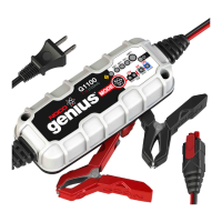
| Model | G1100 |
| Category | Battery Charger |
| Language | English |