9
ENGLISH
230 VAC
50 Hz
24 Vdc
3 W
J4
J1
J3
PE N
L
MAIN
12 45678
COM
OP
M1
COM
OP
M2
CL
LA M P
9 10111213141516171819
OPEN
A
B
STP
CL
OP
FSW
---
+24V
++
-TX
FSW
20 21
W.L.
LO C K
J5
3
230 VAC
max.60W
12 V ac
J6
22
23
24 25
FC A 1
FC C 1
FC A 2
FC C 2
C1
M1
C2
M2
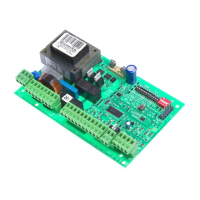
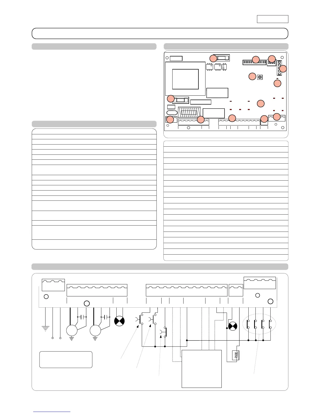
3. LAYOUT AND COMPONENTS
Fig. 1
NB.: Capacitors are supplied with the operators.
Fig. 2
J4
J1
J3
F1
F2
1234
910111256781234
PEN
L
MAIN
12 45678
COM
OP
M1
COM
OP
M2
CL
LA M P
9 10111213141516171819
OPEN
A B
STP
CL OP
FSW
---
+24V
++
-TX
FSW
J2
F
DL10
OP_A OP_B
STOP FSWOPFSWCL
20 21
W.L .
LO C K
J5
22
23
24 25
FCA1
FCC1
FCA2
FCC2
J6
FCA2FCA1
FCC2FCC1
TOTALLY OPEN
OPEN LEAF 1
STOP
1. WARNINGS
Important: Before attempting any work on the control board
(connections, maintenance), always turn off power.
- Install, upstream of the system, a differential thermal breaker
(Residual Current Device) with adequate tripping threshold.
- Connect the earth cable to the appropriate terminal on the J3
connector of the equipment (see fig.2).
- Always separate power cables from control and safety cables
(push-button, receiver, photocells, etc.). To avoid any electric
noise, use separate sheaths or a shielded cable (with earthed
shield).
CONTROL BOARD JA592
4. ELECTRIC CONNECTIONS
F1
F2
J1
J3
J4
J5
J6
LIMIT-SWITCH
2. TECHNICAL SPECIFICATIONS
Power supply 230 V~ ( +6% -10%) - 50 Hz
Absorbed power 10 W
Motor max. load 800 W
Accessories max. load 0,5 A
Electric lock max. load 15 VA
Operating ambient temperature -20 °C +55 °C
Protection fuses 2 (see fig. 1)
Function logics Automatic / Semi-automatic / "Stepped" safety devices /
Semi-automatic B / Dead-man C / "Stepped" semi-automatic
Opening/closing time Programmable (from 0 to 120 s)
Pause time 0, 10, 20, 30, 60, 120 s
Closing leaf delay
0, 5, 10, 20 s
Opening leaf delay 2 s (Can be disabled with the dip-switch)
Thrust force Dip-switch adjustable on 8 levels for each motor
Terminal board inputs Open / Open free leaf / Stop / Limit-switch
Opening safety devices / Closing safety devices / Power supply + Earth
Terminal board outputs Flashing lamp - Motors - 24 Vdc accessories power supply
- 24 Vdc indicator-light - Fail safe - 12 Vac electric lock power supply
Rapid connector Rapid connector 5 pins
Selectable functions Logics and pause times - Thrust force -
Opening and closing leaf delay - Reversing stroke -
Fail safe - Closing safety devices logic - Pre-flashing
Programming key
Simple
or
Advanced
work time learning,
with or without Limit-switch and/or encoder
For connection of
the photocells
and safety
devices, see
paragraph 4.1.
BLUE
BLUE
F
J2
Led
DL10
DS1
DS2
Led OP_A TOTALLY OPEN LED
Led OP_B LED: OPEN LEAF 1 / CLOSE
Led STOP LED STOP
Led FSWCL LED: CLOSING SAFETY DEVICES
Led FSWOP LED: OPENING SAFETY DEVICES
Led FCA1 LED: LEAF 1 OPENING LIMIT-SWITCH
Led FCC1 LED: LEAF 1 CLOSING LIMIT-SWITCH
Led FCA2 LED: LEAF 2 OPENING LIMIT-SWITCH
Led FCC2 LED: LEAF 2 CLOSING LIMIT-SWITCH
DL10 LED: TIME LEARNING SIGNALLING
J1 LOW VOLTAGE TERMINAL BOARD
J2 RAPID CONNECTOR 5 PINS
J3 230 VAC POWER SUPPLY TERMINAL BOARD
J4 MOTORS AND FLASHING LAMP CONNECTION TERMINAL BOARD
J5 INDICATOR-LIGHT AND ELECTRIC LOCK TERMINAL BOARD
J6 LIMIT-SWITCH AND ENCODER TERMINAL BOARD
F1 MOTORS AND TRANSFORMER PRIMARY WINDING FUSE (F 5A)
F2 LOW VOLTAGE AND ACCESSORIES FUSE (T 800mA)
F TIME LEARNING SELECTION PUSH-BUTTON
DS1 1ST GROUP OF MICROSWITCH PROGRAMMING
DS2 2ND GROUP OF MICROSWITCH PROGRAMMING
ATTENTION: when
connecting, observe the
sequence phase/neutral.