RAINBOW 324 C - RAINBOW 524 C - RAINBOW 724 C
ENGLISH
Guide for the installer
Page 7
Thank you for choosing our product. GENIUS is sure you will get
the performances you expect to satisfy your requirements. All our
products are the result of a many years’ experience in the fi eld
of the automated systems, strengthened by being part of a world
leading group in this sector.
In the middle of the manual you will fi nd a detachable booklet
containing all the images for the installation.
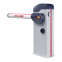
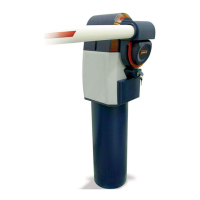
The automated systems of the RAINBOW family are electro-me-
chanical barriers which have been designed and built to control
vehicle accesses.
A handy release device, protected by customised key, enables
you to move the rod by hand in the event of a power cut.
Thanks to the use of 24V motors and of the encoder (standard
supplied), all automated systems of the RAINBOW family are able
to guarantee very high safety levels.
IMPORTANT WARNINGS FOR THE INSTALLER
•
Carefully read the whole manual before beginning to install
the operator.
• Store the manual for future reference.
•
The correct operation and the declared technical specifi ca-
tions are only valid if the instructions given in this manual
are strictly observed and only GENIUS accessories as well
as safety device are used.
• To guarantee an adequate level of safety of the automated
system, the use of a control unit with an adjustable elec-
tronic clutch is necessary due to the lack of a mechanical
clutch .
•
The automated system was designed and built to control
vehicle access. Avoid any other use.
• The operator cannot be used to move safety exits or gates
installed on emergency routes (escape routes).
• Do not transit when the rod is moving.
• Anything not expressly specifi ed in this manual is not per-
mitted.
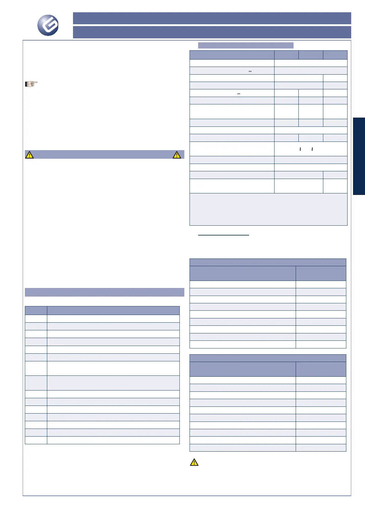
1. DESCRIPTION
With reference to fi gure 1:
Pos. Description
Upright
Panel
Foundation plate (sold as a separate part)
Cover
Control unit enclosure
Rod fi tting cover
Rod (sold as a separate part according to installation
requirements)
Balance spring (sold as a separate part, number and
type according to rod type and to fi tted accessories)
Gearmotor
Encoder
Closing / opening travel limits
Safety switch for opening panel
Red edge (cover for optional luminous strip)
Release device
Compartment for buffer batteries (not supplied)
1.1 TECHNICAL SPECIFICATIONS
RAINBOW Model 324 C 524 C 724 C
Power supply voltage 230V~ 50Hz / 115V~ 60Hz
Motor supply voltage (V
)24
Max. power at thrust (W) 280 480
Motor rated power (W) 160 220
Max. torque at 24V
(Nm) 155 140 370
Operating rated torque (Nm) 30 75 140
Opening / closing nominal time
(sec)
2 to 3 4 to 8 7 to 11
Rod max. length (m)
357
Type and use frequency at 20°C Semi-intensive
Daily max. cycles (cycles) 1500 1000 500
Operating ambient temperature
(°C)
-20 +55
Noise (dBA) <70
Protection class IP 54
Operator weight (Kg) 66 72
Dimensions See fi g. 2
See fi g.
3
Time according to the type of deceleration being set.
Length referred to the passage width, rod length +300mm ap-
prox for Rainbow 324C and Rainbow 524C; rod length +400mm
approx for Rainbow 724C
1.1.1. PRODUCT LIFE
The tables below indicate the product life, expressed in number
of cycles, according to the type of selected rod and to the acces-
sories fi tted to it:
RAINBOW 324 C - RAINBOW 524 C
Rod and accessory
Life (No. of
cycles)
2 to 3 meters 1.500.000
4 meters 1.300.000
5 meters 1.100.000
3 meters with foot 1.300.000
4 meters with foot 1.100.000
5 meters with foot 800.000
3 meters with 2 m skirt 1.300.000
4 meters with 3 m skirt 1.100.000
5 meters with 4 m skirt 800.000
RAINBOW 724 C
Rod and accessory
Life (No. of
cycles)
4 meters 1.300.000
5 meters 1.100.000
6 meters 850.000
7 meters 500.000
4 meters with foot 1.100.000
5 meters with foot 850.000
6.5 meters with foot 500.000
4 meters with 2 m skirt 1.100.000
5 meters with 3.5 m skirt 850.000
6.5 meters with 5 m skirt 500.000
The product life has been calculated at a temperature of
20°C on correctly installed operators, according to the
specifi cations indicated in the instructions.