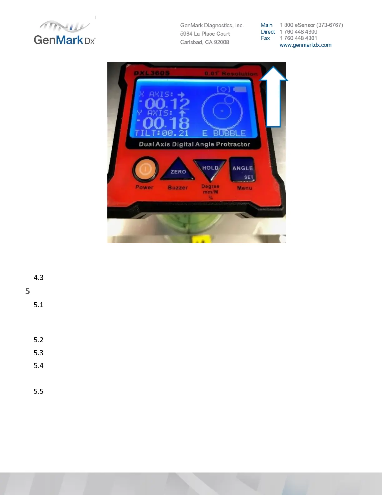
Figure 16 Acceptable Leveling Range from −00.25° to +00.70° (X-axis, left potentially high) and 0° to
-00.70° (Y-axis, back high)
Repeat steps 4.1 - 4.2 for additional towers as needed.
Bay Installation
Check the shipper to ensure the correct number of Bays have been delivered.
Note: If spare bays were shipped or trunk stock bays are available, DO NOT use unless any of the primary
shipped bays are OOBF.
Inspect the packing materials for any signs of physical damage.
Remove the Bays from their respective boxes, one at a time. Inspect each Bay.
Check all visible cabling and tubing for signs of distress, breaks, and disconnections.
Note: If damage is observed, do not install the Bay. Contact GenMark Technical Support for guidance.
Check blister motor lead screw nut and tighten if necessary. See Figure 17 below.