3.2 Servicing
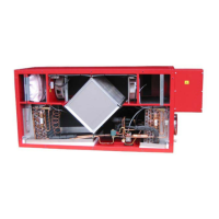
Filters:
When the red lamp on the control panel ashes, the lters
must be changed/cleaned. Stop the unit with the switch
on the unit or the electrical panel. Open the front cover
and take out the lter. When the lter has been changed
or cleaned by shaking it and by removing the worst dirt,
switch on the unit and press the enter button on the
control panel for 10-15 seconds until the Genvex logo
starts ashing again and the equipment is back in normal
operation.
Careful handling of the plates is required. They
have sharp edges and must not be damaged.
Do not vacuum or clean at high air pressure. It
willdamagethelter!
Condensate drain:
When changing the lters in the autumn season check the
condensate drain and tray for blockage by dirt. Fill water
in the condensate tray and check that the water runs out
unhindered. Should this not be the case the drain must
be cleaned. At the same time make sure that the plates of
the evaporators are clean.
Counter current heat exchanger:
Inspect the counter current heat exchanger every three
years. If it is dirty, remove it and wash in warm soapy
water and then rinse, possibly in the bathroom using the
shower head.
Fans:
Every three years check the two fan wheels for dirt. If
they are dirty they must be cleaned with a brush, bottle
washer etc. Please notice that the balance weight of the
fan wheels are not removed causing an unbalance and
thereby a higher noise level and abrasion of the fans.
Supply and extract valves:
Clean the valves by wiping with a dry cloth. Make sure
the valve does not rotate, causing a change in the air
volume.
3. Maintenance
The following instructions must be followed in order to
ensure optimum operation of the Combi:
THE POWER SUPPLY TO THE SYSTEM
MUST ALWAYS BE SWITCHED OFF BEFORE
OPENING THE COVER.
When the unit has been installed for the rst time
make sure the water drains are checked after a few days
to make sure they are performing well.
Environmental considerations
When the unit is being serviced or its operation is
cancelled, please make sure to follow the guidelines
for recovery and disposal of all materials according to
local procedures and laws.
3.1 Connecting to computer
In order for the optima 310 to communicate with
the computer (data logger) the communication box
“Genvex data logger” has to be installed between
the controller and the computer. The data logger is
accessory equipment and can be required at Genvex A/S.
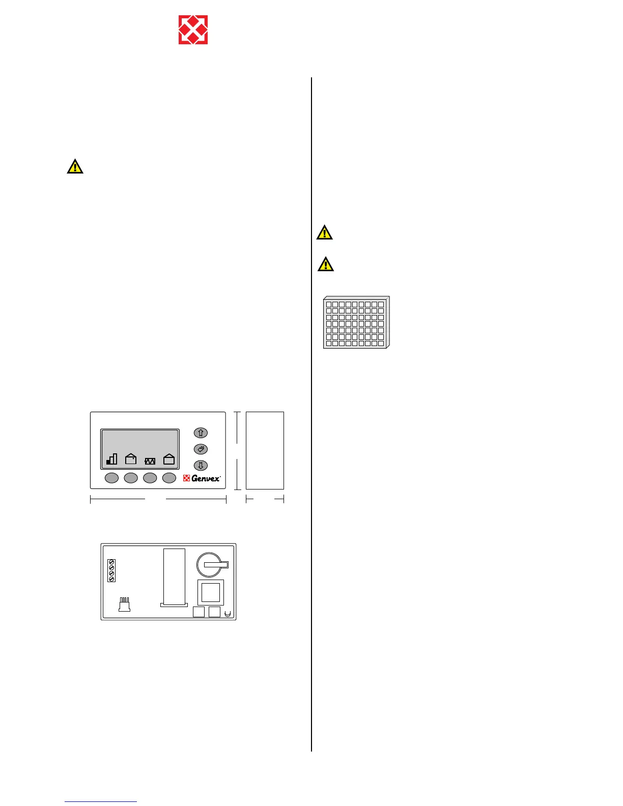
Cable acces (bottom rear)
back side
A: Terminal block. Power connection.
B: Room sensor T2.
C: Communication plug to computer (data logger). CTS unit
D: Data collection IC circuit (Red).
E: Processor control panel.
F: Battery.
G: IC circuit (black).
Between the unit and the control panel a light current
cable 4 x 0.25 mm2 should be mounted. The maximum
cable length is 30 m.