Nozzle Test Bed GERUTEST NTB5
1. Description of Operation
The GERUTEST disposes high thrusts for disposition in
combination with injection valves. Due to its specification
GERUTEST is not capable to boost great volume under high
pressure. Neither pump capacity nor oil storage are available in
adequate measurement for such duties. In its specified
application area the operating medium manages on compressed
air.
The functional principle depends on a proportional active force
pump. The absolute maximum outlet pressure is warranted
through safety limitation on the lower pressure side (see 1. risk
analysis)
For operating the compressed air feed (pressure < 15 bar) will
be connected to GERUTEST, the display verified and start lever
reversed. The compression will be assembled to the adjusted
barrier. The operating power can be readjusted by the pressure
control valve until the required value is shown on the manometer
or the maximum pressure – according to different requirements -
is reached.
When the high pressure is no longer needed the start lever will
be reversed to “0” position. To bleed the lines the manual air
bleed valve must be opened. The high pressure pipe can only
be tooped by discharged lines.
2. Starting and Shutdown
I. O
PERATION
T
EST OF
G
ERUTEST
1) Attach nozzle bed test to base.
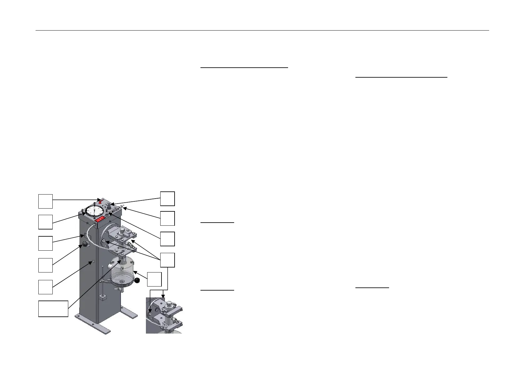
2) Check the display unit
A
for damage and position „0“
indicator.
3) Check oil and oil level gauge
B
-Oil level should be visible to inspection eye.
4) At low oil level fill the device with oil as follows:
4.1) Choose the oil quality by allowance of label
C
on
the tank.
4.2) Open the oil filler neck
D
by turning to the left.
4.3) Pour the oil till oil filler neck.
4.4) Now you close the oil filler neck
D
by turning to the
right.
5) Close the decompression valve
E
by turning to the
right till you reach stop (the valve must be closed
completely).
6) As securing the hose connection with the supplied
locking piece.
7) Turn the cut off cock
F
in position II.
8) Now you connect the compressed air to compressed
air outlet
G
.
ATTENTION: A maximum of 15 bar compressed
air may not be exceeded!
9) Afterwards turn the previously elevated filter pressure
regulator
H
to the right.
10) Put the plug
F
in position I.
11) The pump will start and should build up the pressure.
12) After reaching pressure of 400 bar on the display unit
A put plug F in position II again.
ATTENTION:
Nozzle test plant blocked at 400 bar
or 600 bar (according to
requirements)!
13) The value on the indicator
A
should not be drop
down. This means the high pressure pump is fully
functional.
14) Open decompression valve
E
by turning to the left.
15) The pressure will drip to „0“ bar on indicator
A
.
II. Working with nozzle test bed
1.) The pressurization of the device under test must be
tested against the input of the manufacturer of the
nozzle.
2.) Start with position 3.) to 7.).
3.) Attach screw in unit to injection valve.
4.) Connect hose to screw in unit.
5.) Apply screw in unit to injector body and lock.
6.) Swivel in oil collection container under injection
nozzle.
7.) Place plug
F
in position I.
8.) Examine the gunning chart of the injection nozzle in oil
collection container
I
and setting data of the nozzle
manufacturer.
9.) After checking turn plug
F
to the basic position. The
pump will stop.
10.) Now open decompression valve by turning left.
Pressure indicator
A
will drop to “0” bar.
11.) Thereafter open the hose on the screw in unit of the
injection nozzle and you can remove it from the
injection nozzle.
12.) Now you can start again to check other injection
nozzles.
13.) Should the injection nozzle be defect, that the jet
needle needs to be replaced, this can be done.
13.1) Open both screws
K
on the injector body.
13.2) Turn the injector body 180° (right or left) and
tighten with both screws.
13.3) Now you can open injection nozzle fixed in the
injector body with included special key.
ATTENTION: High pressure hose may only be
connected or removed by opened
bleeder valve
E
. Display unit
A
at
the same time dropped to “0” bar
6 (9)
 Loading...