It is possible to use the relay output as level threshold or alarm in case the reed probe is
not sensing the magnetic float.
In order to access the 2 programming buttons, remove the front cover of the transmitter.
Then connect a reference multimeter to the analogue output pins.
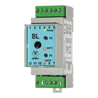
1) Press P2 button for at least 3 seconds, until GREEN led start blinking, and RED
leds blink alternatively.
2) - Use relay as level threshold: Set fluid at the desired level and wait until value
on multimeter is stabilized. Now press and release P1.
- Use relay as alarm: press and release P2.
3) To store acquired relay setting press and release both P1 and P2.
Is it possible to disable relay on the transmitter by executing only step 1) and 3).
Relay settings
4-20mA or 0-10V output calibration
During manufacturing and factory testing, the transmitter is calibrated for 4-20mA or
0-10V output using precise instruments. This calibration should be executed only if a
different output type or range is needed.
During this calibration phase, relay output will be activated for diagnostic purpose. It is
recommended to disconnect wires from pin 1, 2 and 3.
In order to access the 2 programming buttons, remove the front cover of the transmitter.
Then connect a reference multimeter to the analogue output pins.
1) While transmitter is powered off, keep pressed both P1 and P2 buttons and then
power on.
2) Keep both buttons pressed for at least 3 seconds, until GREEN led start blinking:
now it’s possible to release them.
3) RED led below P1 is now on, indicating the output calibration corresponding to the
minimum level.
4) Press P2 for increase and P1 for decrease the output value, until you read on
multimeter the needed value (ex. 0,0Vdc or 4,0mA).
5) Now press both P1 and P2 and release them.
6) OUT RED led is now on, indicating the output calibration corresponding to the
maximum level.
7) Press P2 for increase and P1 for decrease the output value, until you read on
multimeter the needed value (ex. 10,0Vdc or 20,0mA).
8) Now press both P1 and P2 and release them.
9) Both RED led remain on for a few seconds while data are stored in the transmitter.
10) Transmitter reset itself and start working.
0-100% level calibration
In order to access the 2 programming buttons, remove the front cover of the transmitter.
Then connect a reference multimeter to the analogue output pins.
1) Press P1 button for at least 3 seconds, until GREEN led start blinking, and RED
leds blink alternatively.
2) Set fluid level at minimum and wait until value on multimeter is stabilized. Then
press and release P1 button.
3) Now only one of the two RED leds is blinking. Set fluid level at maximum and wait
until value on multimeter is stabilized. Then press and release P2 button.
4) RED leds are now blinking together. Press both P1 and P2 and release them so
that transmitter writes in memory the data acquired.
It is possible to acquire only of the two level settings, by pressing P1 button for minimum
level or P2 button for maximum level and then confirm by pressing both P1 and P2.
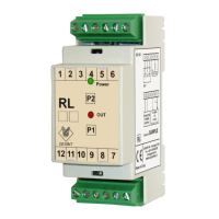
LED signalling
GREEN LED (Power):
ON: transmitter is powered and working
Fast blinking: programming mode
Slow blinking: empty or invalid data in eeprom, transmitter need to be calibrated
(both output and level)
RED LED (Out1 - Out2):
ON: active level threshold
Blinking: programming mode
 Loading...