EasyManua.ls Logo

Gesint RL User Manual

Gesint RL
2 pages
To Next Page IconTo Next Page
Page #1 background imageLoading...
Page #1 background image
It is recommended to use a connection cable of at least 0,5mmq
section and a maximum length of 250mt. Connection cables must
have separate run from power cables.
If the reed probe is installed upside-down, that is with the output
connector near the minimum level, the connection polarity
(PIN 4 and 6) must be inverted to obtain an output matching the
level measured.
In order to use voltage output (0-10V) pin 7 and 8 must be
connected together.
GESINT
®
RL
Level transmitter
for reed probe
RL transmitter convert the level measure from a
GSH reed probe and a magnetic float in a
4-20mA or 0-10Vdc analog output signal.
The output signal of the instruments is
proportional to the distance between minimum
and maximum point set during calibration.
The transmitter is supplied with 1 relay output
that can be used as level threshold or alarm.
Digital calibrations and settings with 2 push
buttons.
The warranty is valid for 12 months from purchase, and expires if instrument is improperly
used or not correctly installed on system.
Warranty
CE mark according to Directive 89/336/CEE, complies with the following harmonised
regulations: EN50081-1, EN 50082-2, EN55022, EN61000-4-2, EN61000-4-3,
EN61000-4-4, EN61000-4-5, EN61000-4-6, EN61000-4-11 and Low Voltage Directive
73/23/CEE and subsequent modifications.
Technical data
GESINT
®
GESINT S.R.L.
Via Perosi, 5 - 20010 Bareggio (MI) - ITALY
Tel. +39-02-9014633 - +39-335-6282615
Fax +39-02-90362295
E-mail: info@gesintsrl.it - WWW.GESINTSRL.IT
Power supply: 24VAC/DC switching
Power consumption: 2VA / 1,8W max
Input signal: Potentiometric
Reed probe voltage: 5 Vdc
Analogue output: 0/4-20mA or 0/2-10V
Output impedance: Max 750Ω (mA) or Min 1KΩ (V)
Relay output: 1 SPDT relay
Mechanical life: min. 10
7
cycles
Electrical life: N.O. @ 3A 250VAC : 5x10
4
N.C. @ 2A 250VAC : 2x10
5
Contact rating: 3A @ 30 VDC (resistive load)
3A @ 250 VAC (resistive load)
Programming: 2 push buttons
Protection: IP20
Storage temperature: from 30 to +80°C
Working temperature: from 20 to +60°C
Relative humidity: from 0 to 85%, no condensate
Installation: 35 mm DIN rail
Electrical connection: Removable terminal board
Dimensions: 90(H) x 35(L) x 60(P) mm
Electrical connection
Rev.2
Question and Answer IconNeed help?

Do you have a question about the Gesint RL and is the answer not in the manual?

Gesint RL Specifications

General IconGeneral
BrandGesint
ModelRL
CategoryTransmitter
LanguageEnglish

Summary

Technical Data

Power Supply and Consumption

Specifies 24VAC/DC switching power supply and consumption of 2VA/1.8W max.

Input Signal and Probe Voltage

Details potentiometric input signal and 5 Vdc reed probe voltage.

Analogue and Relay Outputs

Describes 0/4-20mA or 0/2-10V analogue output and 1 SPDT relay output.

Contact Ratings and Programming

Lists contact ratings for relay and 2 push button programming.

Protection, Environment, and Dimensions

Covers IP20 protection, operating temperatures, humidity, installation, and device dimensions.

RL Transmitter Overview

Functionality and Output Signal

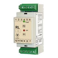
Converts reed probe level to 4-20mA or 0-10V analog output, proportional to distance.

Relay Output Functionality

Features a 1 relay output for level threshold or alarm settings.

Calibration and Settings

Digital calibration and settings are managed via 2 push buttons.

Electrical Connection Details

Cable Recommendations

Use 0.5mmq cable, max 250m. Separate power and signal cables for optimal performance.

Polarity Inversion for Upside-Down Mounting

Invert PIN 4 and 6 if probe is mounted upside-down for correct output.

Voltage Output (0-10V) Setup

Connect pins 7 and 8 together to enable the 0-10V voltage output.

LED Signalling and Calibration

LED Indicators Explained

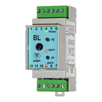
Details GREEN (Power) and RED (Out1-Out2) LED states for operation and programming.

0-100% Level Calibration Procedure

Step-by-step guide to calibrate minimum and maximum fluid levels using push buttons.

Relay Output Configuration

Instructions for setting relay output as level threshold or alarm.

4-20mA or 0-10V Output Calibration

Procedure for calibrating analogue output ranges, with relay activation for diagnostics.

Related product manuals