Do you have a question about the GESTRA NRGT 26-2 and is the answer not in the manual?
Describes hazard symbols indicating dangerous situations or zones.
Details warnings for hazardous situations that could result in death or serious injury.
Details warnings for hazardous situations that may result in death or serious injury.
Details warnings for hazardous situations that may result in minor or moderate injury.
Details warnings for hazardous situations that may result in damage to property or the environment.
Warning about explosion risk in potentially explosive atmospheres.
Warning against using equipment without a proper nameplate.
Warns of scalding danger when removing the level electrode under pressure.
Warns of burn risk from hot level electrodes during maintenance.
Warns of electric shock risk when working on electrical systems.
Warns of danger from hot steam/water escape due to faulty electrodes.
Warns that unauthorized repairs can compromise plant safety.
Explains how to adapt the measuring range during commissioning.
Details how to set parameters and modify factory configurations.
Critical safety warning regarding scalding danger during installation.
Critical safety warning about burn hazards from hot electrodes during installation.
Warning about potential malfunctions due to incorrect installation.
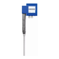
Step-by-step guide for installing the NRGT 26-2 model.
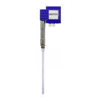
Step-by-step guide for installing the NRGT 26-2s model.
Critical warning about potential damage from rotating the terminal box improperly.
Important notes regarding the electrical connection of the device.
Instructions for connecting the 24V DC power supply to the transmitter.
Details on how to connect the 4-20 mA analogue output.
Pin assignment details for the M12 connector when using non-pre-wired cables.
Pre-commissioning check of the level transmitter's connection.
The step to switch on the supply voltage during commissioning.
Instructions for modifying factory settings if required.
Important notes for the initial commissioning of the device.
Step-by-step guide on selecting and setting parameters on the device.
Notes and best practices for calibrating the level transmitter.
Procedure for calibrating the lower limit (0%) of the measuring range.
Procedure for independent rapid calibration at a specific water level (> 25%).
Warning that faulty equipment compromises system safety.
Critical warning about open circuits in the 4-20 mA current loop.
Critical safety warning regarding scalding danger when taking the unit out of service.
Critical safety warning about burn hazards from hot electrodes during removal.
| Brand | GESTRA |
|---|---|
| Model | NRGT 26-2 |
| Category | Transmitter |
| Language | English |