Do you have a question about the GESTRA NRS 1-2 and is the answer not in the manual?
Specifies compatible GESTRA level electrodes for NRS 1-2 operation.
Highlights risks of electric shock and requirements for qualified personnel.
Details compliance with LV, EMC, and ATEX directives and related requirements.
Directs users to find conformity declarations online or upon request.
Lists package contents and describes the NRS 1-2 level switch's purpose.
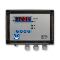
Explains operating modes, test function, and LED indicators for alarms.
Lists GESTRA level electrodes compatible with the NRS 1-2.
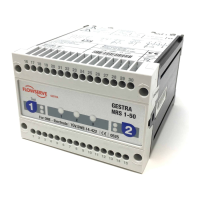
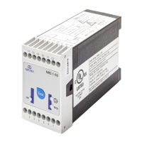
Describes the plug-in unit design and options for control cabinet mounting.
Covers approval numbers, electrode input, and relay output contact ratings.
Details sensitivity, electrode voltage, ambient temperature, and power consumption.
Describes indicators, supply voltage options, and protection rating (IP 40).
Specifies materials used for housing and the unit's weight.
Illustrates the device's name plate with key operational and identification details.
Provides detailed diagrams of the NRS 1-2 unit's physical dimensions.
Shows diagrams with labeled components (A-G) of the NRS 1-2 unit.
Illustrates the front panel showing LEDs (1, 2) and test button (3).
Explains all labels (A-H, 1-3) used in the Design and Functional Elements sections.
Provides step-by-step instructions for mounting on a supporting rail or panel.
Advises on ventilation spacing and lists required tools and components.
Presents diagrams illustrating practical installation steps and component connections.
Specifies suitable cables and maximum lengths based on water conductivity.
Provides critical notes on wiring, terminal bridging, and handling inductive loads.
Presents essential wiring diagrams (Fig. 10, Fig. 11) for connecting the NRS 1-2.
Instructs to verify wiring and apply supply voltage to the unit.
Details the steps to test MIN and MAX alarm functions using LEDs and the test button.
Lists common faults and remedies for low-level alarms and no-alarm conditions.
Lists common faults and remedies for high-level alarms and no-alarm conditions.
Covers safety precautions and proper procedures for removing and disposing of the unit.