EasyManua.ls Logo

GESTRA NRS 1-50 - User Manual

GESTRA NRS 1-50
36 pages
Print Icon
To Next Page IconTo Next Page
Loading...
Original Installation &
Operating Manual
850694-00
Level Switch
NRS 1-50
For TWO electrodes
EN (USA)
English

Other manuals for GESTRA NRS 1-50

Questions and Answers

  • J
    Jason WrightAug 16, 2025
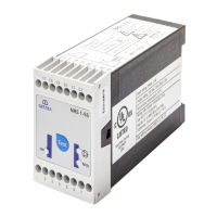
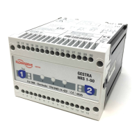
    What to do if LED alarm 1 or 2 and Diagnosis LED 3 are illuminated on GESTRA NRS 1-50?
    • J
      Jessica AndersonAug 16, 2025
      If the LED alarm 1 or 2 and Diagnosis LED 3 are illuminated on your GESTRA Switch, and pressing and holding down key 1 or 2 doesn't resolve the issue, it could be due to a malfunction in the processor or a stand-by fault. Refer to the operating instructions for the logic unit SRL and consider replacing the level switch. It could also indicate an internal voltage fault, in which case you should replace the level switch.
  • K
    Kayla VazquezAug 19, 2025
    Why is the Diagnosis LED 3 flashing on my GESTRA Switch?
    • C
      Cameron ConnerAug 19, 2025
      If the Diagnosis LED 3 is flashing on your GESTRA Switch, it may be due to interference voltage causing a malfunction, or the boiler earth may be without PE. To resolve this, provide screen and earthing, and connect the boiler with PE.
  • A
    anthony65Aug 22, 2025
    What to do if LED alarm 1 and diagnosis LED 1 are illuminated on GESTRA Switch?
    • J
      johnortegaAug 22, 2025
      If LED alarm 1 and diagnosis LED 1 are illuminated on your GESTRA Switch, and pressing and holding down key 1 doesn't resolve the issue, it could indicate a malfunction in the level electrode or level switch, faulty wiring, or a faulty measuring voltage. Check the wiring, measure electrode voltages, clean and, if necessary, exchange the level electrode, and exchange the level switch.
  • N
    nclarkAug 26, 2025
    What to do if Alarm 1 LED and diagnostic LED 1 light up on GESTRA Switch?
    • J
      Janet GarciaAug 26, 2025
      If Alarm 1 LED and diagnostic LED 1 light up on your GESTRA Switch, and you've pressed and held button 1, it could be due to an error in level electrode 1, the level switch itself, wiring, or measuring voltage. You should check the wiring, measure electrode voltages, clean the level electrode (replacing it if necessary), or replace the level switch.
  • B
    Brian PenningtonAug 28, 2025
    What to do if Alarm 2 LED and diagnostic LED 2 light up on GESTRA NRS 1-50?
    • M
      Michael ParkerAug 28, 2025
      If Alarm 2 LED and diagnostic LED 2 light up on your GESTRA Switch, and you've pressed and held button 2, it could indicate an error in level electrode 2, the level switch, wiring, or measuring voltage. You should check the wiring, measure electrode voltages, clean the level electrode (replacing it if necessary), or replace the level switch.
  • R
    Raymond MasseyAug 31, 2025
    What to do if Alarm 1 and 2 LEDs and diagnostic LED 3 light up on GESTRA NRS 1-50 Switch?
    • W
      Whitney SmithAug 31, 2025
      If Alarm 1 and 2 LEDs and diagnostic LED 3 light up on your GESTRA Switch after pressing and holding button 1 or 2, it may indicate a processor error, standby error, or internal voltage error. The suggested solution is to replace the level switch.
  • D
    drakemichaelSep 3, 2025
    What to do if GESTRA Switch shows an error in the level electrode, level switch, wiring, or measuring voltage?
    • J
      Jennifer GalvanSep 3, 2025
      If the GESTRA Switch indicates an error in the level electrode, level switch, wiring, or measuring voltage, you should: – Check the wiring. – Measure the electrode voltages. – Clean the level electrode and replace it if necessary. – Replace the level switch.
  • A
    Amy YoungSep 6, 2025
    Why does my GESTRA Switch show an external voltage error, and the boiler wall has no PE?
    • D
      Diana JonesSep 6, 2025
      If the GESTRA Switch displays an external voltage error and the boiler wall lacks PE (Protective Earth), provide shielding and grounding, and connect the boiler to PE.
  • M
    Morgan ScottSep 9, 2025
    What to do if GESTRA Switch shows a processor error or standby error?
    • S
      Sarah SchmidtSep 9, 2025
      If the GESTRA Switch displays a processor error or a standby error, replace the level switch.
  • C
    Carly JacobsSep 12, 2025
    What to do if GESTRA Switch shows an internal voltage error?
    • J
      John WalkerSep 12, 2025
      If the GESTRA Switch displays an internal voltage error, replace the level switch.

Summary

Usage for the intended purpose

Basic safety information

Required personnel qualifications

Function

Technical data

Rating plate, identification

Factory default settings

Important notes

Safety information

Emphasizes that installation, connection, and maintenance require qualified and trained staff.

Preparing for installation

Installation

Electrical connection

Supply voltage

Specifies the requirement for an external 0.5A fuse for the NRS 1-50 level switch.

Connecting the level electrode

Details the connection procedure for level electrodes, including cable type and shield connection.

Wiring diagram for Class C protection against second faults with automatic prevention of interlock deactivation in the event of malfunction.

Illustrates wiring for Class C protection and automatic prevention of interlock deactivation during malfunctions.

Bringing into service

Checking the switchpoint and function

Details the procedure for testing the switchpoint and verifying the function of the level switch.

Operation, alarm and testing

Fault indications and troubleshooting

Provides guidance on interpreting fault indications, diagnosing issues, and performing troubleshooting steps.

Checking level electrodes

Emergency mode

Emergency mode for water level limiters

Describes how to operate the level switch with a single electrode in emergency situations.

Taking out of service

GESTRA NRS 1-50 Specifications

General IconGeneral
Housing MaterialStainless steel
Float MaterialStainless steel
Nominal sizeDN50
ApplicationLevel monitoring in tanks and vessels
Switching FunctionSPDT (Single Pole Double Throw)
Connection typeFlanged

Related product manuals