Do you have a question about the GESTRA NRS 2-4 and is the answer not in the manual?
The level switch NRS 2-4 is used with level electrode NRG 211 to signal a maximum admissible liquid level.
The level switch is a safety device; only qualified staff may install, wire, and commission it.
The terminal strip of the NRS 2-4 is live during operation, posing an electric shock hazard.
Equipment without its specific name plate must not be commissioned or operated.
The NRS 2-4 meets Low Voltage Directive 2014/35/EC and EMC Directive 2014/30/EC.
The NRS 2-4 must not be used in potentially explosive areas per European Directive 2014/34/EC.
Lists components included for NRS 2-4c and NRS 2-4d, such as the level switch, guide rails, and connectors.
Describes the NRS 2-4 as an amplifier for electrode NRG 211, detecting high water level and malfunctions.
Explains the NRS 2-4's function: power supply, voltage detection, and signal decoding via LEDs.
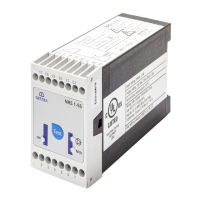
Details the physical design for NRS 2-4c (19" slide-in unit) and NRS 2-4d (spare 19" slide-in unit).
Details input/output circuits, relay contacts, optocouplers, indicators, mains voltage, power consumption, housing, and weight.
Provides a diagram and key measurements (169mm, 128.5mm, 30.48mm) for the NRS 2-4 unit.
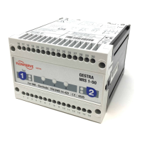
Identifies functional elements like connector A, LEDs (Power, Malfunction, Alarm), and fixing screws F via diagrams.
Steps for mounting guide rails, installing the connector, and fixing the level switch for the NRS 2-4c model.
Steps for inserting and fixing the level switch for the NRS 2-4d model.
Lists the necessary tool: Screwdriver 5.5/100 for installation.
Details required cable types, max length, and presents a wiring diagram (Fig. 3) for the NRS 2-4.
Provides wiring diagram key, safety precautions, connection notes, and required tools for electrical work.
Verify that the NRS 2-4 and electrode NRG 211 are wired correctly according to the diagram.
Apply mains voltage; the green LED 'Power' should illuminate.
Tests for correct LED indication and response to water level changes, including malfunction indicators.
Lists measuring voltages for different operating conditions like electrode malfunction or submersion.
Provides fault finding steps for issues like 'Power' LED not illuminated or malfunction LEDs illuminated.
Troubleshooting for high water level when only the 'Power' LED is lit, covering electrode and preamplifier issues.
Details on conformity with European Directives and availability of declarations on the internet.