Do you have a question about the GESTRA NRS 1-9 and is the answer not in the manual?
Specifies the correct application of the NRS 1-9 with level electrode NRG 16-36.
Emphasizes that only qualified staff should install, commission, and maintain the equipment.
Warns of the risk of electric shock from live terminal strips during operation.
Advises users to check the name plate for technical specifications and not to operate without one.
Details ATEX compliance for use in potentially explosive atmospheres with Zener barriers.
Lists the items included in the product package for the NRS 1-9.
Provides a summary of the self-monitoring water level controller and its application.
Explains the two-channel circuit, self-monitoring, and testing functions of the controller.
Identifies the related system components, specifically the NRG 16-36 level electrode.
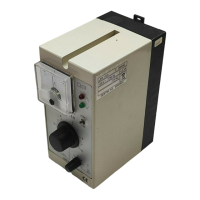
Describes the physical design of the NRS 1-9 as a plug-in unit for control cabinets.
States that safety is not impaired by corrosion when used as intended.
Illustrates and explains the information found on the equipment's name plate.
Presents the physical dimensions of the NRS 1-9 controller with diagrams.
Provides a key to identify components labeled in design and functional diagrams.
Instructions for mounting the controller on a standard supporting rail.
Instructions for mounting the controller onto a panel.
Lists necessary tools for installation.
Defines components and labels used in installation diagrams.
Illustrates practical examples of controller installation.
Important safety and operational notes regarding wiring connections.
Additional information and recommendations for wiring.
Specifies tools required for wiring tasks.
Schematic representation of the electrical connections for the controller.
Procedure for adjusting the controller's sensitivity settings.
Tools needed for basic adjustments.
Verification of electrical connections before power-up.
Procedure for applying mains voltage to the controller.
Tests to verify the low-level limiting function.
Tests to verify the high-level limiting function.
Tests for the water level control functionality.
Critical safety warning regarding live terminal strips during operation.
Guide to diagnose and resolve common operational problems.
Statement confirming compliance with European directives and standards.
| Brand | GESTRA |
|---|---|
| Model | NRS 1-9 |
| Category | Controller |
| Language | English |