EasyManua.ls Logo

GESTRA LRGT 16-2 - User Manual

Default Icon
72 pages
Print Icon
To Next Page IconTo Next Page
Loading...
Installation & Operating Manual
EN
English
Conductivity Controller LRR
Visual Display and Operating Unit URB
LRR 1-52
LRR 1-53
URB 55
850645-01

Table of Contents

Other manuals for GESTRA LRGT 16-2

Questions and Answers

  • J
    Jerry BurnsAug 9, 2025
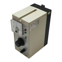
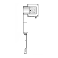
    What to do if GESTRA Measuring Instruments equipment fails to work?
    • M
      michaelpettyAug 9, 2025
      If your GESTRA Measuring Instruments equipment isn't working, start by checking the power supply and all electrical connections to rule out a power failure. If the issue persists, the electronic circuit board might be faulty, so you should check or replace it. Also, ensure the earth connection to the vessel isn't interrupted; clean the seating surfaces and screw in the conductivity transmitter with a new sealing ring, avoiding insulation of the electrode thread.
  • V
    Veronica HarrisAug 17, 2025
    Why is GESTRA Measuring Instruments equipment not working accurately?
    • Y
      ypeckAug 17, 2025
      Inaccurate readings from GESTRA Measuring Instruments can stem from several causes. Start by checking for dirt on the transmitter measuring electrode(s) and clean them if necessary. For LRGT 16-2 models, ensure the spacer disc PEEK 8 is correctly positioned. Also, if the conductivity reading is higher than expected, reduce the temperature coefficient during commissioning or the cell constant during operation. Conversely, if the reading is lower, increase these values. If adjusting the cell constant doesn't resolve the issue, remove the conductivity transmitter and clean the measuring surface or electrodes.
  • D
    Don ScottAug 31, 2025
    How to prevent electric shock when working on GESTRA Controller electrical systems?
    • P
      Pamela GrayAug 31, 2025
      To avoid electric shock when working on GESTRA Controller electrical systems: * Always switch off the voltage to the equipment before working on the terminal strips (installation, electrical connection, disassembly). * Disconnect all poles of the supply cable from the mains and secure them so they cannot be switched back on. * Before starting work, check that the system is not carrying live voltage.
  • E
    Ellen HaneyNov 22, 2025
    What to do if LEDs indicate a malfunction in GESTRA Measuring Instruments?
    • D
      Denise CareyNov 22, 2025
      If the LEDs on your GESTRA Measuring Instruments are indicating a malfunction, consider these potential issues: * Check the electrode wires for interruptions or exposed measuring surfaces/electrodes, ensuring connections are secure at the electronic circuit board (terminal lugs 1-4). Also, check the water level and installation. * Inspect the electrode wires for short circuits, again checking connections at the electronic circuit board (terminal lugs 1-4). * If the value is below the set value of 0%, check the water level and installation. * If the value is above the set value of 100%, set a larger measuring range. * If the temperature in the terminal box exceeds 85°C, ensure the ambient temperature does not exceed 70°C. * For open or short circuits in wires to the resistanc...

Summary

Safety, Warnings, and Intended Use

Basic safety notes

Provides essential safety precautions related to electrical systems and faulty equipment.

Product Overview and Technical Data

Technical data - LRR 1-52, LRR 1-53

Provides detailed technical specifications for the LRR 1-52 and LRR 1-53 conductivity controllers.

Technical data - URB 55

Provides detailed technical specifications for the URB 55 visual display and operating unit.

Installation and Electrical Connections

Installing the LRR 1-52, LRR 1-53 conductivity controller

Provides instructions for installing the LRR 1-52/1-53 conductivity controller.

Installing the URB 55

Provides step-by-step instructions for installing the URB 55 unit.

Connecting the URB 55

Details how to connect the URB 55 unit, including ports and pin assignments.

Safety notes for electrical connection

Provides critical safety notes regarding electrical connections and wiring.

Wiring diagram - LRR 1-52 conductivity controller

Provides the wiring diagram for connecting the LRR 1-52 controller.

Wiring diagram - LRR 1-53 conductivity controller

Provides the wiring diagram for connecting the LRR 1-53 controller.

Electrical connection - LRR 1-52, LRR 1-53

Provides detailed instructions for the electrical connection of LRR controllers.

Connecting the data line between the conductivity controller and the URB 55

Instructions for connecting the data line between the controller and URB 55.

Operation and Configuration

Changing the equipment settings

Instructions on how to change the equipment settings using the code switch.

Operation and navigation

Explains how to operate and navigate the URB 55 unit.

Entering parameters using the virtual keypad

Explains how to use the virtual keypad for parameter entry.

Parameter input with password protection

Details how password protection is used for parameter input.

GESTRA LRGT 16-2 Specifications

General IconGeneral
Output Signal4-20 mA
Protection ClassIP 65
Housing MaterialAluminum
Connection SizeDN15
MaterialStainless steel

Related product manuals