
S
Sarah WilkinsAug 7, 2025
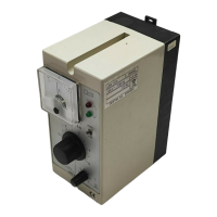
How to prevent electric shock when working on GESTRA URB 55 Controller electrical systems?
- GGrant RodriguezAug 7, 2025
To avoid electric shock when working on GESTRA Controller electrical systems: * Always switch off the voltage to the equipment before working on the terminal strips (installation, electrical connection, disassembly). * Disconnect all poles of the supply cable from the mains and secure them so they cannot be switched back on. * Before starting work, check that the system is not carrying live voltage.