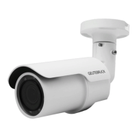
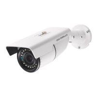
G-Cam/EWPC-5240 + EWPC-5250 Bullet IP Camera Quick Guide
• The camera must be installed by qualified persons. The installation should comply with local regulations.
• Do not replace the batteries of the camera independently. There is a risk of explosion if the battery is replaced
with an incorrect type. Used batteries must be disposed of according to local regulations.
• If you want to use an external power source, ask the camera manufacturer for a suitable device.
1 RJ-45 - For network and PoE connections
2 Audio I/O
Green Audio Out / Mic Out (Line Out)
Two-way audio transmission
Pink Audio In / Mic In (Line In)
3
Alarm I/O
(5-pin Terminal Block)
1
Alarm In 2+
Alarm connection
#Do NOT connect external
power supply to the alarm I/O
connector of the IP camera.
2
Alarm In -
3
Alarm In 1+
4
Alarm Out -
5
Alarm Out +
4
Power (DC 12V / AC 24V)
(2-pin Terminal Block)
1 DC 12V − AC 24V 1
Power connection
2 DC 12V + AC 24V 2
microSD Card Slot / Default Button
The positions of the microSD card slot and default button are shown as follows. For details on how to remove the
front body of the camera, refer to the microSD Card Slot / Default Button section in the User's Guide.
microSD Card Slot
Insert the microSD card into the card slot to store videos and snapshots. Do not remove the microSD card when the
camera is powered on.
Note: It is not recommended to record to the microSD card in 24/7 mode as most microSD cards are not
designed for permanent recording.
Please follow the instructions below for cable connections.
Power Connection
Please use a DC 12V / AC 24V adaptor and connect it to the 2-pin terminal block of the All-in-One cable and the power
outlet. Alternatively, connect the Ethernet cable to the RJ-45 connector of the All-in-One cable, and plug the other end
of the cable to a Power Sourcing Equipment (PSE) switch.
Ethernet Cable Connection
Connect one end of the Ethernet cable to the RJ-45 connector of the All-in-One cable, and plug the other end of the
cable to the network switch or PC.
NOTE: In some cases, Ethernet crossover cable might be needed when connecting the camera directly to the
PC.
NOTE: Check the status of the link indicator and the activity indicator LEDs. If the LEDs are unlit, please check
the LAN connection.
Green Link LED indicates good network connection.
Orange Activity LED flashes for network activity indication.
IMPORTANT: We recommend operating IP cameras only in isolated networks or behind suitable firewalls.
This Quick Start Guide describes how to quickly install and connect the G-Cam/EWPC-52x0 Bullet IP Camera. For
more information, refer to the IP Camera Installation/User Guide.
Installation Notices
All-in-
One Cable
Default Button
Press the default button with a proper tool for at least 20 seconds to restore the system.
Cam
era Cabling
Initial login to the IP camera
The first time you access the IP camera, you will be prompted to change your password. You must perform this
step to continue.
For more information, refer to the user manual of the IP camera.
NOTE: Passwords must be at least 12 characters long, with an uppercase letter, a lowercase letter,
and a numeric character or a special character ~@#$%^&*_-+=:;<>
No. Connector
Pin
Definition
Remarks