DUA TR CZ SK SLO RO P PL LT LV EST GR RUS FIN DK S E I NL F GBH
Wireless colour surveillance system CSF
Control elements
Monitor (fi g. A)
1 Camera 1 switch
2 Automatic camera change
3 Camera 2 switch
4 ON/OFF switch
5 Camera switch interval: setting 10 - 50 seconds
6 Volume
7 Power supply 9 V connection socket
8 Loudspeaker
9 Attachment wall holder/table stand
10 Wall holder
11 Table stand
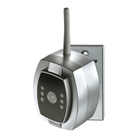
Camera (fi g. B)
1 Aerial
2 Camera lens
3 IR LEDs
4 Microphone
5 Wall holder
6 Power supply 6 V
7 Switch camera 1/camera 2
Power supply (fi g. C)
1 For camera (6 V)
2 For monitor (9 V)
Safety information
All warranty claims will be null and void in the
event of any damage or loss caused by failure
to observe these operating instructions.
We accept no liability for any consequential
losses or damage. We accept no liability for any
personal injury or material damage caused by improper
use or by failure to observe the safety advice. In these
cases the guarantee and warranty are invalidated. For
safety and authorisation purposes it is not permitted to
carry out any adaptation or conversion of the device.
Montagem
If you are unsure of how to assemble, connect and
install the device or if you are in doubt as to how to
operate it, please do not assemble, connect or install
the device yourself but contact a qualifi ed specialist.
You have purchased a high quality wireless
surveillance system. The transmission can be
dampened or negatively a ected by various objects.
This applies in particular to obstacles made of metal
or reinforced concrete or walls, and also if the camera
and the monitor are mounted very close to one another
(< 50 cm). Check reception prior to mounting and
select a suitable site. Check the position of the camera
when mounting (fi g. E). The microphone opening (B4)
must face downwards.
The monitor can either be attached to the wall (fi g. F1)
using wall holder A10 or placed on a table top (fi g. F2)
using table stand A11. Clip the wall holder or table
stand into the appropriate attachment A9 on the
monitor in the selected position.
Setting the camera (fi g. D)
Set the camera switch 1 to "ON" on the fi rst camera.
Switches 2 and 3 must be switched to "OFF" (fi g. D1).
If you are using the second camera as well, set camera
switch 2 to "OFF". Switches 1 and 3 must be switched
to "ON" (fi g. D2). Connect the power supply plug (fi g.
C1) to the camera connection B6 and insert the plug
into the appropriate socket. Connect the power supply
plug C2 to the monitor connection A7 and insert the
plug into the appropriate socket.
Starting up/operating
Press the ON/OFF key (A4). The LED in the key lights
up if there is mains power and the monitor displays the
image from camera 1.
The volume is adjusted using the loudspeaker
controller (A6). Direct the camera as required.
If a second camera is also connected, press the
Camera 2 (A3) key and set as required. The images
from cameras 1 and 2 can be shown in sequence.
Press the automatic camera switch key (A2). The
interval can be infi nitely adjusted from 10 - 50 sec.
using the switch interval controller (A5). An LED
is integrated into keys A1, A2, A3 and A4 to
indicate the settings.
The cameras are fi tted with IR LEDs to allow persons
and objects to be identifi ed within a range of
approx. 1 m, even in the dark (for technical reasons
these images are only available in black and white).
Optional accessories (fi g. G)
2. Camera
The same design as the camera supplied with the set.
Connection as described above.
Please order: Camera art. no. 085169,
Power supply (6 V) art. no. 085176
2. Additional monitor
The camera image can be shown on any number of
monitors.
Please observe the maximum range.
Please order: Monitor art. no. 085152,
Power supply (9 V) art. no. 085183
Recycling instructions
This device must not be disposed of with unsorted
household waste. Owners of old devices are re-
quired by law to dispose of this device correctly.
Contact your town council for further information.
Troubleshooting – practical tips
Problem Cause Solution
No picture and ON/OFF Is the power supply/monitor Connect power supply/monitor
LED does not light up connected?
No picture and ON/OFF Power supply is faulty/ Take power supply/monitor for
LED does not light up monitor is faulty inspection if necessary
No picture/faulty picture Is the camera power supply connected? Check plug
Is the camera switch set? Check camera switch
Poor radio reception Reposition the camera/monitor
Camera faulty Check camera
Poor reception/poor image Camera too far from monitor Adjust distance
Camera too close to monitor
Picture rotated by 180° Camera has been mounted upside Mount camera with the
down microphone facing down
Picture has green tinge Night image, caused by IR LEDs Normal for night time surveillance
Whistling sound Camera is too close to monitor Reposition camera
No sound/sound too quiet Volume is set too low Set the volume
No sound Camera microphone is faulty Check the volume
The device is authorised for sale within the EC.
Gutkes GmbH hereby declares that this wireless colour surveillance system complies with the basic
requirements and other relevant specifi cations of EC directive 1999/5/EC.
To view the conformity declaration in full, please go to:
www.gev.de
Technical data
Monitor
Dimensions approx. W 120 mm x H 126 mm x D 32 mm
Display type TFT, visible diagonal measurement 87 mm
Resolution 480 x 234 pixels
Operating voltage 9 V
Operating power consumption approx. 500 - 605 mA
Operating temperature range -10 °C to +45 °C
Camera
Dimensions approx. W 65 mm x H 80 mm x D 84 mm
Camera module CMOS 1/3“
Resolution 628 x 582 pixels
Min. lighting < 3 Lux (at a distance of < 50 cm)
Operating voltage 6 V
Operating power consumption approx. 80 - 100 mA
Operating temperature range -10 °C to +45 °C
Range min. 50 cm, max. 80 m (free air)
Protection type IP 44
We reserve the right to make technical and visual modifi cations without prior notice.
4 5
Gutkes GmbH
Rehkamp 13
30853 Langenhagen
Germany
Fax: +49 (0)511/95 85 805
www.gev.de
service@gev.de
 Loading...