EasyManua.ls Logo

GEYA GRT8-X1 - User Manual

Default Icon
2 pages
Print Icon
To Next Page IconTo Next Page
Loading...
-1-
Wiring diagram
Instruction Manual
Digital display time relay
GEYA ELECTRICAL CO.,LTD
Add:Wenzhou Brige Industrial Zone,Beibaixiang Town,
Yueqing,Zhejiang,China 325603
Tel:0086-577-62711079
Fax:0086-577-62711751
Mobile:0086-13567770207
E-mail:sale@cnyeya.com
Web:www.geya.net
General
Applications
-Multifunctional time relay can be used for industrial equipment, lighting control,
heating element control, motor, fan control.
-With 20 delay modes, the delay range covers 0.1 seconds to 99 days.
Function Features
-20 delay modes:
-5 delay modes controlled by power supply
-13 delay modes controlled by signal
-ON, OFF mode
-Ultra wide delay range, 0.1 seconds - 99 days can be set.
- Relay status is indicated by LED.
- 1-MODULE,DIN rail mounting.
Model and connotation
Panel Diagram
Technical parameters
GRT8-X1
Digital display
Un
Un
Digital Setting Time Relay
Number of contacts
1:1×SPDT;
2:2×SPDT;
GRT8
A230:AC230V ;
W240:AC/DC12V-240V;
Rated control supply voltage
GRT8 Series
X
Function
Supply terminals
AC/DC 12-240V(50-60Hz)
A1-A2
Voltage range
Burden
Voltage range
AC 0.09-3VA/DC 0.05-1.7W
AC 230V(50-60Hz)
AC max.6VA/1.3WAC max.6VA/1.9W
-15%;+10%
Power input
Supply voltage tolerance
Time ranges
0.1s-99day,ON,OFF
Key setting
Time setting
Time deviation
Repeat accuracy
1%
0.2%-set value stability
0.05%/,at=20(0.05%℉at=68)
1×SPDT2×SPDT
250VAC/24VDC
Output
500mW
red LED
1×10
max.200ms
Min.breaking capacity DC
Switching voltage
Current rating
Output indication
Mechanical life
Electrical life(AC1)
Reset time
-20 to+55(-4℉to131
-35 to+75(-22℉to158
Din rail EN/IEC 60715
IP40 for front panel/IP20 terminals
any
solid wire max.1×2.5or 2×1.5/with sleeve max.1×2.5(AWG 12)
90×18×64mm
1×SPDT:W240-62g,A230-60g
2×SPDT:W240-82g,A230-81g
EN 61812-1,IEC60947-5-1
Operating temperature
Storage temperature
Mounting/DIN rail
Protection degree
Operating position
Overvoltage cathegory
Pollution degree
Dimensions
Weight
Standards
20 functions
W240
A230
1×10
5
1×16A(AC1)
2×16A(AC1)
Temperature coefficient
GRT8-X1GRT8-X2
Button (Set)
-4-
http://www.geya.net
Disposal of Electrical Waste
All electrical waste should be
disposed of in compliance with
current WEEE regulations.
Caution
The products must be installed by qualified electricians. All and
any electrical connections of the time relay shall comply with
the appropriate safety standards.
NOTE: the use case is for reference only to understand the working principle of the relay. The actual application should be wired
according to the actual needs.
CASE1:
The working mode is set to 07 and accessed through the
sensor (PNP). When the sensor senses the signal, the relay
acts (15-18 is closed) and the ventilation fan works. When the
sensor loses the signal, the relay disconnects after a delay t
(15-18 is disconnected) and the ventilation fan stops working.
SensorPNP
Brown
Black
Fan
CASE 2:
The working mode is set to 03, the ventilation fan is turned on
for 10 hours and turned off for 1 hour, and the ventilation fan
is cycled on and off.
AC220V
~~
CASE 3:
When the working mode is set to 02, the time relay is powered
on (15-18 is closed), the contactor is closed, the water pump
starts to work, the delay t reaches, the relay is disconnected
(15-18 is disconnected), the contactor is disconnected, and the
water pump stops working.
PUMP
LED
CASE 4:
The working mode is set to 08, press the trigger button, the time
relay acts (15-18 is closed), turn on the LED, delays t, the relay
is disconnected (15-18 is disconnected), and the LED is closed.
AC220V
~
~
Trigger button
Fan
Output indication(red)
Button (UP)
MD
R
15
1618
15
1618
25
2628
28
95
4.2
MD
GR T8-X1
R
0V
24V
Blue
AC220V
~
~
AC220V
~
~
Dimensions(mm)
Examples
Question and Answer IconNeed help?

Do you have a question about the GEYA GRT8-X1 and is the answer not in the manual?

Summary

General Information

Applications

Describes typical uses of the time relay for industrial equipment and control.

Function Features

Lists key features like 20 delay modes, ultra wide delay range, and LED status indication.

Model and Connotation

Explains the naming convention for different relay models and configurations.

Technical Parameters and Diagrams

Panel Diagram

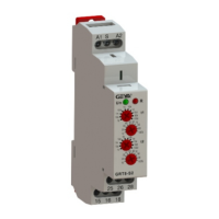
Illustrates the physical layout of the digital display time relay controls and indicators.

Wiring Diagram

Shows the electrical connections for the relay, including terminals for power and output.

Product Adjustment Procedures

Fast Adjustment of Delay Time

Details how to quickly set delay times using short and long presses of buttons.

Delay Function Setting

Explains how to enter and set the specific delay function mode for the relay.

Function Mode Descriptions

Function 01: On Delay (Power On)

Relay delays and closes output contact after power-on delay time t.

Function 02: Interval (Power On)

Relay output contact closes immediately on power-on, then disconnects after delay t.

Function 03: Repeat Cycle (Starting Off)

Cyclical delay operation: closes after t1, disconnects after t2, repeats until power off.

Function 04: Repeat Cycle (Starting On)

Cyclical delay operation: closes after t2, opens after t1, repeats until power off.

Function 05: Pulse Generator (Power On)

Relay closes on power-on, disconnects after t2, then closes after t1, repeating until power off.

Function 06: On Delay with External Control

Relay delays after external control signal connection, closes output contact after delay t.

Function 07: Off Delay with External Start

Relay closes immediately on external signal, delays on signal disconnection, then disconnects.

Function 08: Pulse I with External Start

Relay closes and delays on external signal, disconnects after t. Signal restart resets delay.

Function 09: Pulse II with External Start

Relay closes on external signal disconnection, delays, disconnects. Signal changes reset delay.

Function 10: On;Off Delay with External Control

Delays for t1 on signal connection, delays for t2 on signal disconnection.

Function 11: Latching Relay

Output contact state changes upon energization and control terminal connection.

Function 12: Repeat Cycle with External Control (Starting Off)

Cyclical delay: closes after T1, disconnects after T2, repeats on external control.

Function 13: Repeat Cycle with External Control (Starting On)

Cyclical delay: opens after t2, closes after t1, repeats on external control.

Function 14: Pulse Generator with External Start

Relay delays for T1, closes output, then disconnects after T2.

Function 15: Start-Stop

Relay delays for T1 on S trigger, closes output; delays for T2 on next S trigger, disconnects.

Function 16: Double Delay Off with External Control

Delays for t1, disconnects. Delays for t2 after S disconnection, disconnects.

Function 17: On Delay I by External Start

Relay delays on S connection, closes output. Disconnects when relay is de-energized.

Function 18: On Delay II with External Start

Relay delays on S trigger, closes output. Restarting S resets delay.

Function 19: Always ON

Relay is closed when energized, and disconnected when de-energized.

Function 20: Always OFF

Relay is disconnected regardless of energization state.

Overview

This document describes the GEYA GRT8 Series Digital Display Time Relay, a versatile device designed for various industrial and control applications.

Function Description

The GEYA GRT8 Series Digital Display Time Relay is a multifunctional device capable of controlling industrial equipment, lighting, heating elements, motors, and fans. It offers 20 distinct delay modes, covering a broad delay range from 0.1 seconds to 99 days. These modes include:

  • 5 delay modes controlled by power supply: These modes activate based on the presence or absence of power to the relay. Examples include "On Delay (Power On)" where the output contact closes after a set delay t once power is applied, and "Interval (Power On)" where the output contact closes immediately upon power-on and disconnects after delay t.
  • 13 delay modes controlled by signal: These modes respond to an external control signal (S terminal). Examples include "Latching relay" where the output contact state changes with each connection of the S terminal, and "Repeat cycle with external control (Starting Off)" where the relay cycles between closed and open states based on delays t1 and t2 as long as the S terminal is connected. Other signal-controlled modes include "On delay with external control," "Off delay with external start," "Pulse I with external start," "Pulse II with external start," "On/off delay with external control," "Pulse generator with external start," "Start-stop," "Double delay off with external control," "On delay I by external start," and "On delay II with external start."
  • ON, OFF mode: These modes provide continuous ON or OFF states, such as "Always ON" where the relay is continuously closed when energized, and "Always OFF" where the relay is continuously disconnected regardless of power.

The relay's status is indicated by an LED. The device is designed for 1-MODULE, DIN rail mounting.

Important Technical Specifications

The GRT8 Series time relay is available in two contact configurations: GRT8-X1 (1×SPDT) and GRT8-X2 (2×SPDT).

Supply Terminals: A1-A2 Voltage Range: AC/DC 12-240V (50-60Hz) Burden: AC 0.09-3VA/DC 0.05-1.7W Power Input:

  • GRT8-X1: AC max. 6VA/1.9W
  • GRT8-X2: AC max. 6VA/1.3W Supply Voltage Tolerance: -15%; +10% Time Ranges: 0.1s-99day, ON, OFF Time Setting: Key setting Time Deviation: <1% Repeat Accuracy: 0.2% - set value stability Temperature Coefficient: 0.05%/°C (at 20°C) Output:
  • GRT8-X1: 1×SPDT, 1×16A (AC1)
  • GRT8-X2: 2×SPDT, 2×16A (AC1) Switching Voltage: 250VAC/24VDC Min. Breaking Capacity DC: 500mW Output Indication: Red LED Mechanical Life: 1×10⁷ Electrical Life (AC1): 1×10⁵ Reset Time: max. 200ms Operating Temperature: -20°C to +55°C (-4°F to 131°F) Storage Temperature: -35°C to +75°C (-22°F to 158°F) Mounting/DIN Rail: DIN rail EN/IEC 60715 Protection Degree: IP40 for front panel/IP20 terminals Overvoltage Category: III Pollution Degree: 2 Max. Cable Size (mm²): Solid wire max. 1×2.5 or 2×1.5 / with sleeve max. 1×2.5 (AWG 12) Dimensions: 90×18×64mm Weight:
  • GRT8-X1: W240-62g, A230-60g
  • GRT8-X2: W240-82g, A230-81g Standards: EN 61812-1, IEC60947-5-1

Usage Features

The GRT8 Series time relay features a digital display for easy monitoring and setting. Setting Delay Time:

  • Fast Adjustment: A short press of the "Set" button enters the fast setting interface. Subsequent short presses adjust the parameter value, while a long press enables rapid adjustment. Values exceeding 99 will reset to 0.
  • Delay Function Setting: A long press of the "MD" button (3 seconds) enters the function mode parameter setting interface. Here, users can select from the 20 available functions (01-20). Within this interface, short presses adjust parameter values, and long presses enable rapid adjustment. If no key operation occurs within 60 seconds, the device automatically exits the setting mode. Users can also press and hold the "MD" button for 3 seconds to exit and save settings.
  • Time Base Setting: The device allows setting the time base for delays (e.g., seconds, minutes, hours, days, or fractions thereof). This option may not be available for single delay time modes.
  • Timing Display Mode: Users can select between "Positive timing" and "Count down" display modes.

Wiring Diagram: The manual provides clear wiring diagrams for both 1×SPDT and 2×SPDT configurations, illustrating connections for A1, A2 (supply), S (control signal), and the output contacts (15, 16, 18 for SPDT; 15, 16, 18, 25, 26, 28 for 2×SPDT).

Example Use Cases: The manual illustrates practical applications:

  • Case 1 (Mode 07, PNP Sensor): When a PNP sensor detects a signal, the relay acts (15-18 closed), activating a ventilation fan. When the signal is lost, the relay disconnects after a delay t, stopping the fan.
  • Case 2 (Mode 03): The ventilation fan cycles on for 10 hours and off for 1 hour.
  • Case 3 (Mode 02): Upon power-on, the relay closes (15-18), activating a water pump. After delay t, the relay disconnects, stopping the pump.
  • Case 4 (Mode 08, Trigger Button): Pressing a trigger button activates the relay (15-18 closed), turning on an LED. After delay t, the relay disconnects, and the LED turns off.

Maintenance Features

Caution: All products must be installed by qualified electricians, and all electrical connections must comply with appropriate safety standards. Disposal of Electrical Waste: All electrical waste should be disposed of in compliance with current WEEE regulations.

GEYA GRT8-X1 Specifications

General IconGeneral
BrandGEYA
ModelGRT8-X1
CategoryRelays
LanguageEnglish

Related product manuals