30
Connecting components
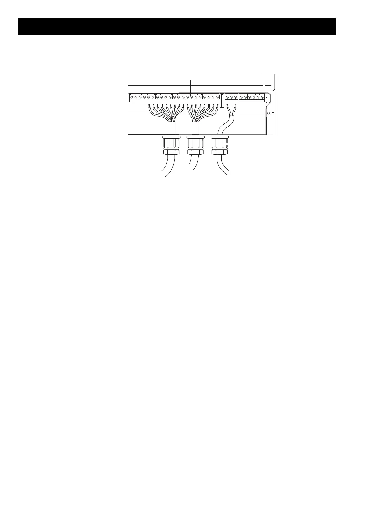
1. Break out the openings in the case required for the lines.
2. Insert cable glands (2) (not included in the delivery) to achieve the required
protection type (see table below).
3. Feed the cables through the case and the cable glands into the RWA-Emergency
Power Control System.
4. Feed the cables to the wiring terminals (1).
The enclosure of the RWA Emergency Power Control System without cable lead-in
fulfils degree of protection IP54.
The degree of protection of cable glands with sealing ring is also IP54.
Thus, the maximum possible degree of protection for the enclosure is achieved by
using cable glands with sealing ring.
The recommended sequence for connecting the components is as follows:
1. Connect the RWA switch, smoke sensor and heat differential sensor for the alarm
group.
2. Connect the drives and ventilator switches (possibly timer switch) from ventilator
group 1.
3. Connect consecutively the drives and ventilator switches (possibly timer switches)
from the other ventilator groups.
4. Connect external equipment: Rain/wind sensor, fire alarm system, floating
(potential-free) contacts for Alarm, Fault and Window Open.
Check connections Before connecting to the mains and to the battery, check the following:
• the component connections
• the configuration (jumper settings)
• that the cable clamps are firmly fixed
765432198765412121213
321
1
2
 Loading...