Do you have a question about the GEZE MBZ300 and is the answer not in the manual?
Explains warning symbols (DANGER, WARNING, CAUTION) for material damage and injuries.
General specifications, software configuration by qualified personnel, and insulation measurement.
Responsibilities for workplace security, qualified personnel, and electrical precautions.
Annual testing, use of genuine parts, and adherence to statutory regulations.
Warning about fire hazards and actions for malfunctions during a fire.
Purpose of the unit for ventilation and smoke extraction in dry rooms.
Lists various functions like controlling drives, natural ventilation, processing alarms, and data logging.
Describes hardware configuration and software configuration flexibility.
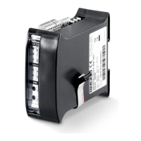
Lists and describes various modules like PM, PME, CM, SM, DM, WM, ERM.
Table of available standard central units with their specifications.
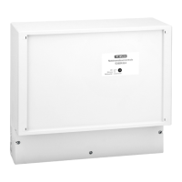
Steps for checking delivery, fastening housing, and configuring the central unit.
How to select switching power supply units, power modules, and batteries.
Diagrams and measurements for module space on DIN rails.
Table with dimensions and weights of different battery types.
Instructions on the correct order of module placement on the DIN rail.
Procedure for readdressing modules after configuration changes.
Details on connecting internal power supply, batteries, and switching power supply units.
CAUTION for connecting batteries and ensuring polarity.
WARNING for connecting mains voltage by a qualified electrician.
Formula and table for calculating cable lengths for drives.
Procedure for inserting the CAN module into the CM module.
Instructions for setting jumpers on CAN modules for bus termination.
Diagram and recommendations for CAN module wiring.
Checks before putting the system into operation.
General operating principles, manual triggering, and ventilation control.
Restricting window width, rain/wind control, and automatic step control.
Triggering alarms manually and automatically, and system response.
Functions and displays of the Power module PM.
Functions and displays of the Power module extension PME.
Functions and displays of the Control module CM.
Functions and displays of the Sensor module SM.
Functions and displays of the Drive module DM/DME.
Functions and displays of the Weather module WM.
Wiring diagram for connecting wind and rain sensors.
Wiring for wind-direction-dependent control.
Functions and displays of the Relay module ERM.
Wiring diagram for the Relay module ERM.
Display behavior during alarm triggering and fault conditions.
Overview of configuration possibilities using software.
Tasks for regular maintenance of the control unit.
Troubleshooting guide for common problems.
Technical specifications for electrical data and connections.
Table of module power consumption and operating conditions.
| Output voltage | 24 V DC |
|---|---|
| Ambient temperature | -5°C to +45°C |
| Operating Temperature | -5°C to +45°C |
| Storage Temperature | -20°C to +70°C |
| Operating voltage | 230 V AC |