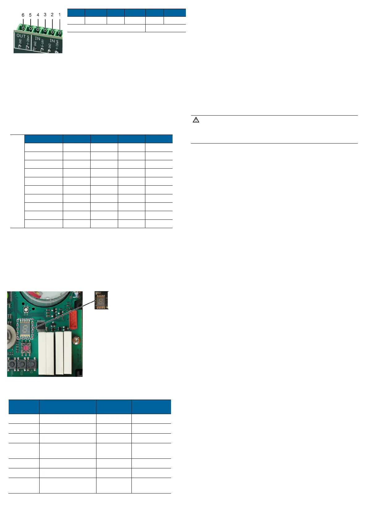
1 2 3 4 5 6
4-20 mA
Ground
0-10V Ground
4-20 mA Ground
IN OUT
6 Settings motor current monitoring
The current monitoring function monitors the motor current. If the motor
current is higher than the pre-set value, an error is reported and the actuator
will remain in place. The setting is done via the left BCD switch marked
“CurrentMon.” on the PCB.
Motor Current Monitoring [mA]
BCD EA25 EA45 EA120 EA250
0 25 25 50 50
1 100 300 300 400
2 150 350 400 500
3 200 400 500 600
4 250 450 600 700
5 300 500 700 800
6 400 600 800 1000
7 500 700 900 1200
8 600 900 1000 1500
9 (factory setting) 700 1100 1200 1800
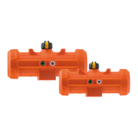
7 Error message
An error can trigger the following:
The 7-segment display on the main board illuminates; see illustration
below. If the positioner PCB is installed, the respective LED lights up red on
the BCD switch, if its set value is exceeded.
The ready-to-operate signal will be off (terminals 5,6 NO contact)
LED flashes yellow (except in case of power outage)
Assignment of error codes for error messages
If the positioner PCB is installed, the following error codes can be displayed:
Error code Description
Signal „Ready-
to-operate“
EA response
Setpoint error None
Actual value error None
Setpoint reversed polarity None
Actual value reversed
polarity
None
Setpoint short circuit None
Actual value short circuit None
Actuator has run into
engine current limit
No Stops
* If the feedback is not connected the error LED will show an actual value error. This can
be avoided by placing a resistor (supplied) between terminal 5 and 6 of the positioner.
Remove the resistor to use the feedback.
For further error codes of the main board, see instruction manual of the electric actuator
type EA 25-250.
Acknowledge error message
Check the cause of fault, if necessary, carry out relevant maintenance.
NOTE!
The message can be eliminated while the supply voltage is still connected
or the actuator is briefly disconnected from the mains voltage (does not
work with cycle monitoring).
Error can be acknowledged via the „SET“ button on the main board.