Chapter 5 Parameters
VFD-E Series
Revision August 2006, 01EE, SW--PW V1.03/CTL V2.03 5-101
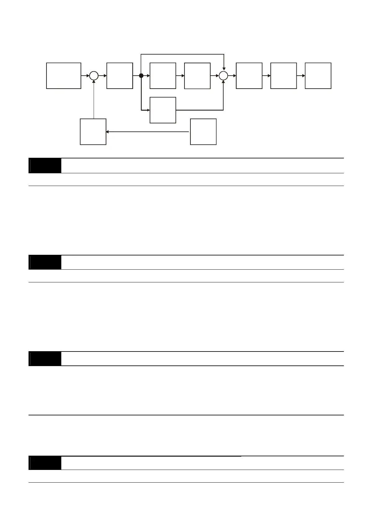
The complete PID diagram is in the following:
P
10.02
I
10. 03
D
10. 04
10. 05
10.10
10. 07
10.06
10.01
Setpoint
Input Freq.
Gain
PID
feedback
Integral
gain
limit
Output
Freq.
Limit
Digital
filter
Freq.
Command
10.07
PID Output Frequency Limit
Unit: 1
Settings 0 to 110 % Factory Setting: 100
This parameter defines the percentage of output frequency limit during the PID control. The
formula is Output Frequency Limit = Maximum Output Frequency (Pr.01.00) X Pr.10.07 %.
This parameter will limit the Maximum Output Frequency. An overall limit for the output
frequency can be set in Pr.01.07.
10.08
PID Feedback Signal Detection Time
Unit: 0.1
Settings 0.0 to d 3600 sec Factory Setting: 60.0
This parameter defines the time during which the PID feedback must be abnormal before a
warning (see Pr.10.09) is given. It also can be modified according to the system feedback
signal time.
If this parameter is set to 0.0, the system would not detect any abnormality signal.
10.09 Treatment of the Erroneous Feedback Signals (for PID and PG feedback error)
Factory Setting: 0
Settings 0 Warning and RAMP to stop
1 Warning and COAST to stop
2 Warning and keep operating
AC motor drive action when the feedback signals (analog PID feedback or PG (encoder)
feedback) are abnormal according to Pr.10.16.
10.10
Gain Over the PID Detection Value
Unit: 0.1
Settings 0.0 to 10.0 Factory Setting: 1.0


 To Next Page
 Loading...