Appendix B Accessories
VFD-E Series
Revision August 2006, 01EE, SW--PW V1.03/CTL V2.03 B-11
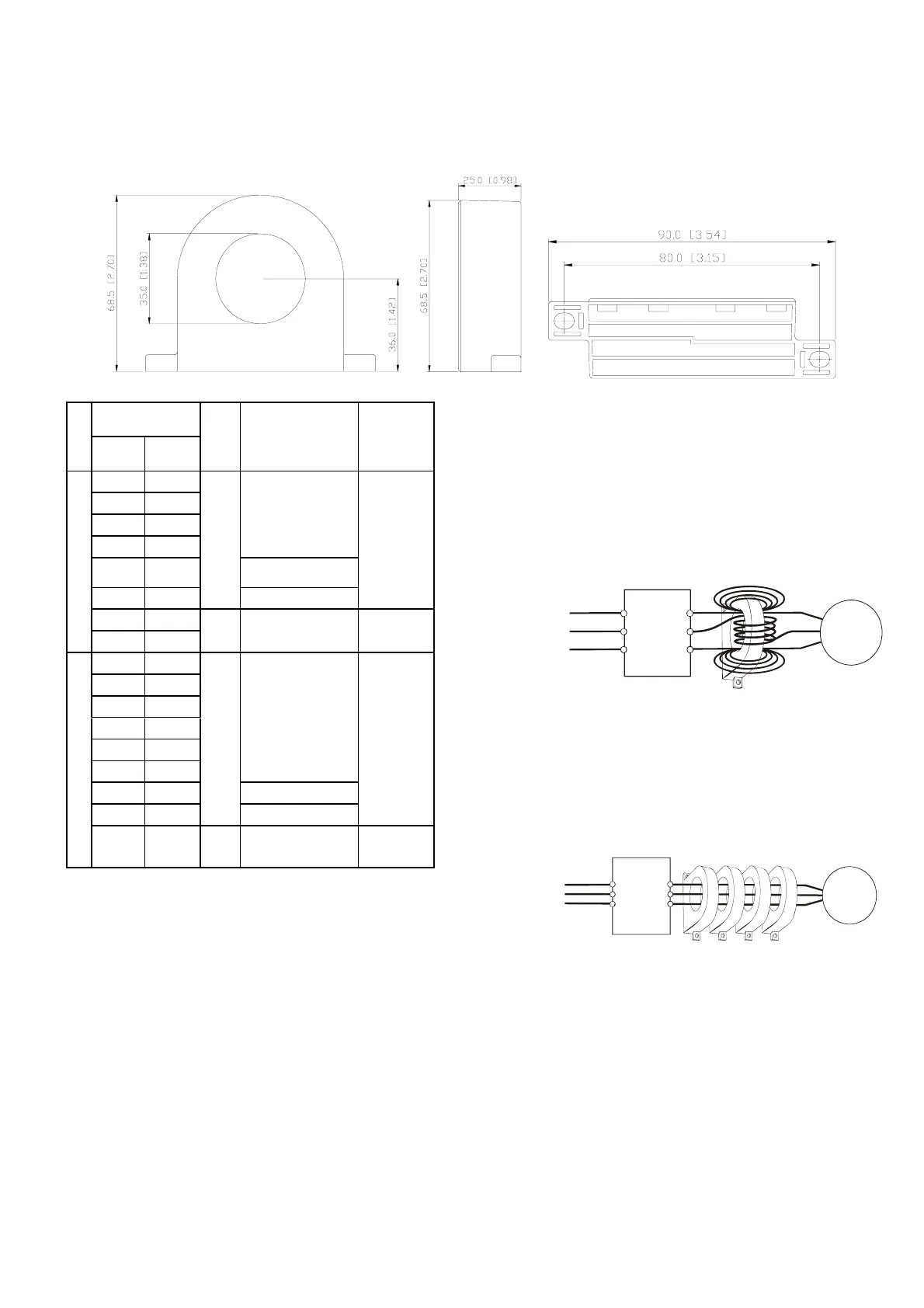
B.4 Zero Phase Reactor (RF220X00A)
Dimensions are in millimeter and (inch)
Motor
HP kW
Qty.
Recommended
Wire Size (mm
2
)
Wiring
Method
1/4 0.2
1/2 0.4
1 0.75
2 1.5
0.5 - 5.5
3 2.2 3.5 - 5.5
5 3.7
1
5.5
Diagram
A
7.5 5.5
115V/230V Series
10 7.5
4 8
Diagram
B
1/4 0.2
1/2 0.4
1 0.75
2 1.5
3 2.2
5 3.7
0.5 - 5.5
7.5 5.5 3.5 - 5.5
10 7.5
1
5.5
Diagram
A
460V Series
15 11 4 8 - 14
Diagram
B
Power
Supply
Zero Phase Reactor
MOTOR
U/T1
V/T2
W/T3
R/L1
S/L2
T/L3
U/T1
V/T2
W/T3
R/L1
S/L2
T/L3
Power
Supply
Zero Phase Reactor
MOTOR
Diagram B
Please put all wires through 4 cores in
series without winding.
Diagram A
Please wind each wire 4 times around the
core. The reactor must be put at inverter
output as close as possible.


 To Next Page
 Loading...