Chapter 3 Start Up
VFD-E Series
Revision August 2006, 01EE, SW--PW V1.03/CTL V2.03 2-15
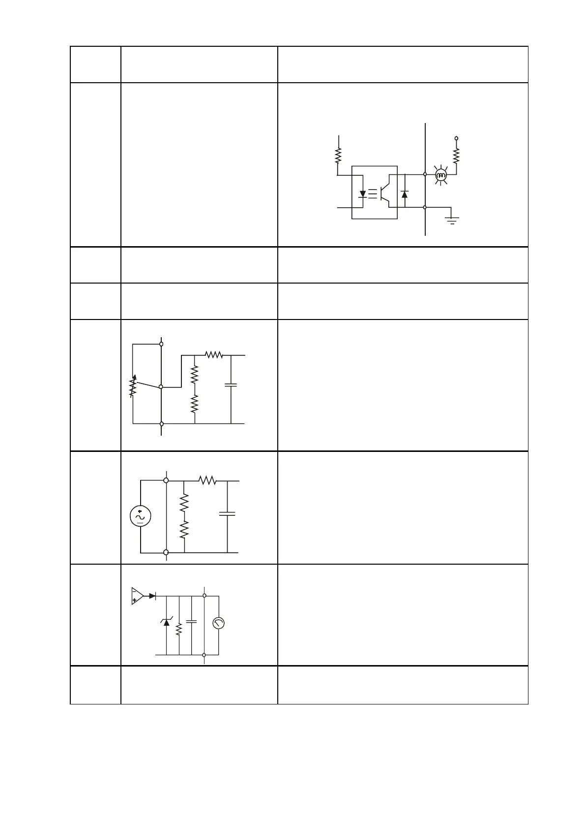
Terminal
Symbol
Terminal Function
Factory Settings (NPN mode)
ON: Connect to DCM
MO1
Multi-function Output 1
(Photocoupler)
Maximum 48VDC, 50mA
Refer to Pr.03.01 for programming
MO1-DCM
Mo1
MCM
Max: 48Vdc
50mA
internal circuit
MCM Multi-function output common Common for Multi-function Outputs
+10V Potentiometer power supply +10VDC 20mA
AVI
Analog voltage Input
ACM
AVI
+10V
internal circuit
AVI circuit
Impedance: 47kȍ
Resolution: 10 bits
Range: 0 ~ 10VDC =
0 ~ Max. Output Frequency
(Pr.01.00)
Selection: Pr.02.00, Pr.02.09, Pr.10.00
Set-up: Pr.04.14 ~ Pr.04.17
ACI
Analog current Input
ACM
ACI
internal circuit
ACI circuit
Impedance: 250ȍ
Resolution: 10 bits
Range: 4 ~ 20mA =
0 ~ Max. Output Frequency
(Pr.01.00)
Selection: Pr.02.00, Pr.02.09, Pr.10.00
Set-up: Pr.04.18 ~ Pr.04.21
AFM
Analog output meter
AFM
ACM
0~10V
Max. 2mA
potentiometer
ACM circuit
internal circuit
0 to 10V, 2mA
Impedance: 20kȍ
Output current 2mA max
Resolution: 8 bits
Range: 0 ~ 10VDC
Function: Pr.03.03 to Pr.03.04
ACM
Analog control signal
(common)
Common for AVI, ACI, AFM
Control signal wiring size: 18 AWG (0.75 mm
2
) with shielded wire.
 Loading...