Chapter 5 Parameters
VFD-E Series
Revision August 2006, 01EE, SW--PW V1.03/CTL V2.03 5-45
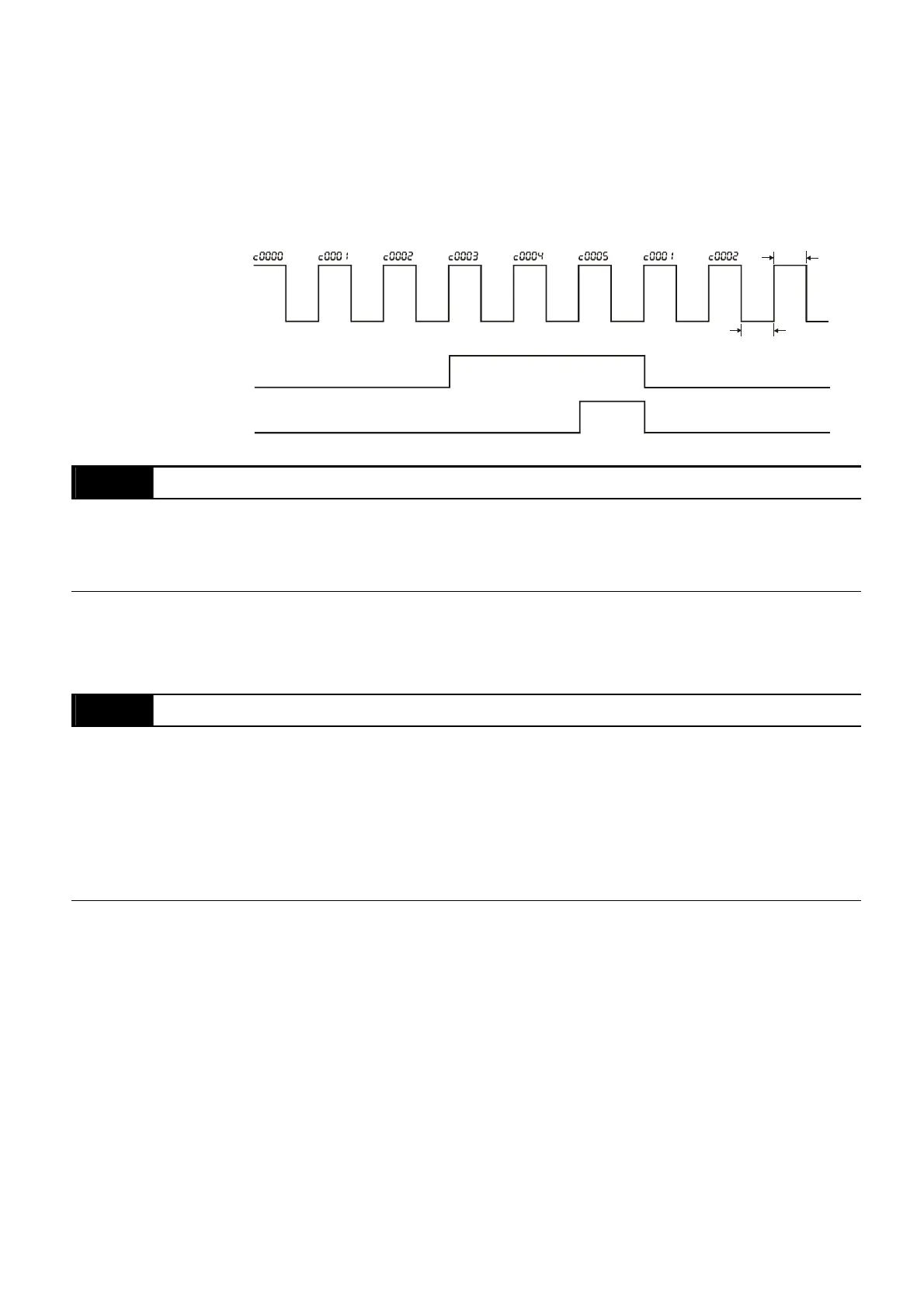
When the counter value reaches this value, the corresponding multi-function output terminal
will be activated, provided one of Pr.03.00 to Pr.03.01 set to 11 (Preliminary Count Value
Setting). This multi-function output terminal will be deactivated upon completion of Terminal
Count Value Attained.
The timing diagram:
Terminal Count Value
(Pr. 03.00~Pr. 03.01=10)
Preliminary Count Value
(Pr. 03.00~Pr. 03.01=11)
Display
(Pr.00.04=1)
TRG
Counter Trigger
The width of trigger signal
should not be less than
2ms(<250 Hz)
2msec
2msec
Ex:03.05=5,03.06=3
03.07 EF Active when Terminal Count Value Attained
Factory Setting: 0
Settings 0 Terminal count value attained, no EF display
1 Terminal count value attained, EF active
If this parameter is set to 1 and the desired value of counter is attained, the AC drive will treat
it as a fault. The drive will stop and show the “EF” message on the display.
03.08 Fan Control
Factory Setting: 0
Settings 0 Fan always ON
1 1 minute after AC motor drive stops, fan will be OFF
2 Fan ON when AC motor drive runs, fan OFF when AC motor drive
stops
3 Fan ON when preliminary heatsink temperature attained
This parameter determines the operation mode of the cooling fan.


 To Next Page
 Loading...