Chapter 5 Parameters
VFD-E Series
Revision August 2006, 01EE, SW--PW V1.03/CTL V2.03 5-53
04.18 Maximum ACI Frequency (percentage of Pr. 01.00) Unit: 0.1
Settings 0.0 to 100.0% Factory Setting: 100.0
04.19 ACI Terminal Mode Selection
Factory Setting: 0
Settings 0 ACI
1 AVI2
04.20 Minimum AVI2 Voltage Unit: 0.1
Settings 0.0 to 10.0V Factory Setting: 0.0
04.21 Minimum AVI2 Frequency (percentage of Pr.1-00) Unit: 0.1
Settings 0.0 to 100.0% Factory Setting: 0.0
04.22 Maximum AVI2 Voltage Unit: 0.1
Settings 0.0 to 10.0V Factory Setting: 10.0
04.23 Maximum AVI2 Frequency (percentage of Pr.1-00) Unit: 0.1
Settings 0.0 to 100.0% Factory Setting: 100.0
Please note the ACI/AVI switch on the AC motor drive. Switch to ACI for 4 to 20mA analog
current signal (ACI) (Pr.04.19 should be set to 0) and AVI for analog voltage signal (AVI2)
(Pr.04.19 should be set to 1).
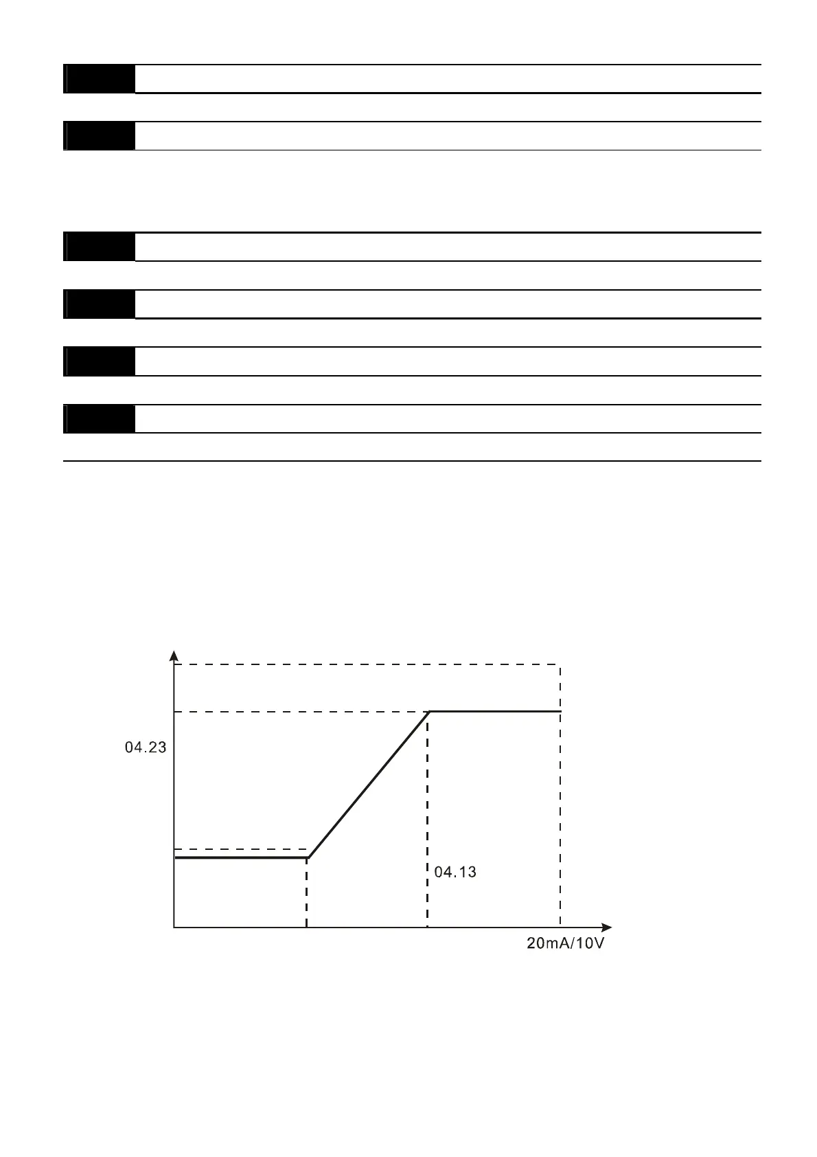
The above parameters are used to set the analog input reference values. The min and max
frequencies are based on Pr.01.00 (during open-loop control) as shown in the following.
01.00
analog input
04.14
04.18
04.12
04.16
04.21
04.11
04.15
04.20
04.17
04.22


 To Next Page
 Loading...