KUDA
11
UK
Encoder
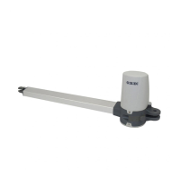
KUDA 150
24 Vdc
100 W (~1000 N)
4 A (~1000 N) MAX
360 mm
24 Vdc 2600 rpm
1000 N
-20°C + 60°C
IP 44
If fitted on blind/flush panel doors
it is mandatory to use an electric lock
Integrated into the motor
intensive
20 mm/s
KUDA 200
1500 N
2 m 2.5 m
400 mm
150 Kg 200 Kg
Electric system setup
Set up the electric system as shown in fig.1 referring to the electric system regulations and other national regulations
in force. Keep the mains power connections clearly separated from the service connections (photocells, sensitive
frames, control devices, etc.).
The main components are:
1- Antenna; screened coaxial cable
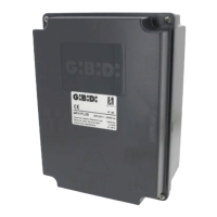
2- Electronic control unit container
3- Electric lock; 1 mm² 2-core (2x1) cable
4- Key selector; 0,5 mm² 3-core (3x0,5) cable
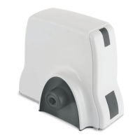
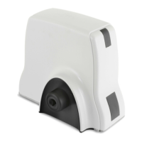
5- 24Vdc operators:
- 1,5 mm² 2-core (2x1,5) cable power supply WHITE = + YELLOW = -
for a cable length of 6 m max., over it’s necessary increase the cable section.
-0,5mm² 3-core (3x0,5) encoder cable.
6- Omnipolar magnetothermal and differential switch with minimum contact opening of 3 mm
220-230V/50-60Hz control unit power line: min. 1,5 mm² 3-core cable (3x1,5)
(adhere to the regulations in force)
7- 24V flashing light; 0,75 mm² 2-core (2x0,75) cable
8- Connector blocks
9- Photocell transmitter; 0,5 mm² 2-core (2x0,5) cable
10- Photocell receiver; 0,5 mm² 4-core (4x0,5) cable
A- Opening mechanical end-stop.
B- Closing mechanical end-stop.
ELECTRICAL EQUIPMENT
Supply voltage
Power absorbed
Current absorbed
Electric motor
Useful travel
Max thrust/traction force
Operating temperature
Frequency of use (%)
Degree of protection
Maximum leaf length
Linear velocity
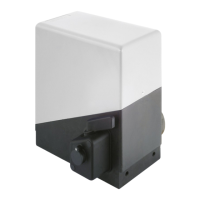
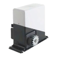
Operator
Type
Irreversible electromechanical with worm screw
TECHNICAL DATA
Maximum leaf weight
CAUTION: It is important that an omnipolar magnetothermal and differential switch with a
minimum contact opening of 3 mm be fitted upstream of the control unit.
 Loading...