Error Indications
8 VA @ 265 VAC
50 to 500 ms
50/60 Hz
110 - 240 VAC/DC
Supply Voltage (Un)
Supply Tolerance
Supply Frequency
Power Consumption
Reset Time
-20% to +10% of Un
Password 60(Default Disabled)
Sensor Inputs (IEC)
Sensor Measurement
Range
Measurement
Accuracy
Resolution
Temperature Unit
Signal Sampling Time
Front Keypad
°C/°F selectable
2 ms
1°c Fixed
+/-0.5% of full scale
TC (J-type):
-5 to 750°C OR 23 to 999°F
TC (K-type):
-20 to 850°C OR -4 to 999°F
RTD (Pt-100):
-100 to 650°C OR -148 to 999°F
Menu Password
Thermocouple (J & K)
RTD (Pt-100, 3-wire)
≥ 40 msKey de-bounce time
Functional Characteristics:
Supply Characteristics:
Technical Specifications:
Connection Diagram:
PID TEMPERATURE
CONTROLLER:
SERIES: PR-43
Features:
4 Keys as ESC ( ), DOWN ( )
UP ( ), ENTER ( )
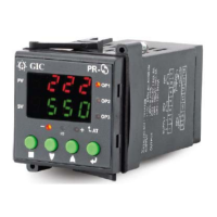
Front Facia:
151G12B (Relay : ) 5A(NO), 3A(NC), 1C/O
ORDERING INFORMATION:
151H12B (SSR Drive : )12VDC, 30mA max
Mechanical Dimensions (in mm):
151G12B/151F12B
151H12B
151G12B
151F12B
15LL002_05
Mode Functionality:
OFF OFF
OFF OFF
OFF OFF
0nA - HEAT
0nA - COOL
0ns - HEAT
0ns - COOL
Parameter
Proportional
Band (Pb)
Adjustment
Decrease ‘Pb’
Increase ‘Pb’
Problem Occured
PV not reach SP/Slow response
High overshoot or Oscillations
Sbr
ovr
unr
eat
nat
Sensor open/Break error
Over range error
Under range error
Error in Auto-tuning
Auto-tuning not finished
within 10 hour
1. Displays the ‘Process Value’ & ‘Menu’.
2. : “ESC” key (
3. : Scroll “DOWN” key.
4. : Scroll up key
(Press for >2sec to view controller output).
5. : “Enter” key(Press 2sec for to view menu).
6. OP1: LED indication for relay output.
7. STATUS: LED indication for Auto tuning ON &
if PV value is ±3°C of SP.
8. ‘°F’: This LED indicates ‘°F’ unit setting.
9. + : press “ESC” key for 2 sec to view SP then
simultaneously press “DOWN” key to decrement SP value.
10. :
Press for >2 sec to view set point).
And release the “ESC” key to set the New SP value.
press “ESC” key for 2 sec to view SP then
simultaneously press Up key to increment SP value.
And release the “ESC” key to set the New SP value.
+
Contact Arrangement
Contact Rating
Relay Output Characteristics: (151G12B/151F12B)
1 C/O (SPDT)
5A(NO),
3A(NC),
RES. @
250VAC/
30VDC
151F12B (Relay ): 10A 1C/O
Dear Customer,
Thank you for purchasing ‘PID Temperature Controller from
GIC. To avoid problems & damages, please read leaflet
carefully before operating the unit.
Highly Accurate Performance.
Luxurious Single 3-digit LED Display.
Wide supply range:110-240VAC (Un),-20 to +10% of Un.
Front keypad with 4 keys.
Thermocouple (J & K)/RTD 3-wire (Pt-100) sensor inputs.
Auto tune PID indication.
Control Modes: PID, ON-OFF Asymmetric, ON-OFF
Symmetric.
°C & °F temperature unit selectable
Control Output: Relay & SSR Drive (Individual products)
Note:
Caution:
Installation should be done by skilled person only.
When extending the thermocouple lead wires, always use
thermocouple compensation wires for wiring.
For RTD sensor, use a wiring material with a small lead
resistance (5Ω max per line) & no resistance differentials
among 3 wires.
Product should be cleaned regularly to avoid blockage of
ventilating parts.
Clean the product with a clean soft cloth. Do not use
isopropyl alcohol or any other cleaning agent.
Use of contactors is recommended if load exceeds the
contact rating. Please see Inductive load category.
For Thermocouple (J & K): To make output ON ensure
that, CJC setting is ON.
When replacing the sensor, please turn OFF the power.
Product innovation being a continuous process, we reserve
the right to alter specifications without
any prior notice.
User is recommended to ensure the suitability of the
product for the intended application
151H12B
Control output
Relay
SSR Drive
Relay
In case of complaint, contact us on 020 - 30680011 or E-mail us o‘service@gicindia.com’
ON/OFF Control: Parameters regarding ON/OFF control
are listed in group “rEg”. This type of control can be set by
programming parameter “con”= OnS for ON-OFF action
with symmetric hysteresis OR OnA for ON-OFF action with
asymmetric hysteresis. It drives the output programmed
as coP [in 0p1], depending on the measured temperature
value, on set point, function mode (Fun) and on the
hysteresis (Hys).
In case of reverse action i.e. HEAT being set on par.
“FUn” in “rEg” menu, the controller activates the output
when the process value “PV” goes below [SP-HYS]. It
deactivates the output when the PV goes above “SP+HYS”
in case of symmetric ON-OFF control and above “SP” in
case of Asymmetric ON-OFF control. Similarly in case of
direct action i.e. COOL being set on par. “Fun”, the controller
activates the output when the process value “PV” goes
below ‘sP-Hys’ & deactivates the output when “PV” goes
above ‘sP+Hys’ in case of symmetric ON-OFF control &
“SP” in case of Asymmetric ON-OFF control.
PID Control: Parameters regarding PID control are listed
in group “rEg”. This type of control can be set by
programming parameter “con”= PID for PID action.
A PID controller depending upon the effective setpoint“SP”,
function “fun” and on the instrument’s PID algorithm the
control output is calculated. The PID control algorithm
foresees the setting of following parameter:
pb: Proportional band, rs: Manual reset,int: integral Time,
der: derivative Time
Proportional band (Pb) is the area around set point
where controller is actually controlling the process; output
is at some level other than 100 or 0%. ‘Pb’ is expressed in
terms of 'ºc/ºF'. If controlling is not Satisfactory by using
default ‘Pb’ value, following adjustment can be done in 'Pb'.
Cycle time (Ct): Also known as duty cycle; Total length of
time for controller to complete one ON/OFF cycle.
E.g.: If Ct=20 sec, TON=10 sec & TOFF=10 sec, then it
represents a 50 % power output. In this case, controller will
cycle ON & OFF while within the set proportional band 'Pb'.
Manual reset(rs): Manual reset is not visible for On-OFF if
“int” value is not equal to zero. when “int” value is equal to
zero then manual reset(rs) is visible for PID.
Integral time (int): this value is in minute, not visible for
On-OFF control.
Derivative time (der): this value is in seconds, not visible
for On-OFF control.
Rate (rte) & Offset (oft): Product can be re-calibrated
according to application needs, by using par. “oFt” and “rte”.
If “rte” = 1.00, then using par “oFt”, it is possible to set
positive or negative offset that is simply added to the value
read by the probe.
If the offset set is not to be constant for all measurements,
it is possible to operate the calibration on any of two points.
In this case, in order to decide which values to program on
par. “oFt” and “rte”, the following formulae must be applied:
“rte” = (y2-y1)/(x2-x1)
“oFt” = y2 - rate*x2
10A RES.
@250VAC
/30VDC
Mounting
Weight (Un-Packed)
IEC 60974-5-1 (2 kV)
IEC 60068-2-1
IEC 60068-2-2
IEC 60068-2-6 (5g)
IEC 60068-2-27 (40g, 6ms)
IEC 60068-2-27 (30g, 15ms)
IEC 61010-1
UL 508 (>50 kΩ)
UL 508 (< 3.5 mA)
IEC 60974-5-1 (Level IV)
Other Characteristics:
Safety Compliance:
Environmental Compliance:
Dielectric Strength
(Input & Output)
Single Fault
Insulation Resistance
Leakage Current
Cold Heat
Dry Heat
Vibration
Repetitive Shock
Non-Repetitive Shock
Impulse
‘48 x 48’ mm Panel Mounting
120 gm
(Input & Output)
Operating Position
Harmonic Current
IEC 61000-3-2 (Class A)
IEC 61000-3-3 (Class A)
IEC 61000-4-2 (Level II)
IEC 61000-4-3 (Level III)
IEC 61000-4-4 (Level IV)
IEC 61000-4-5 (Level IV)
IEC 61000-4-6 (Level III)
IEC 61000-4-8 (Class 4)
IEC 61000-4-11
CISPR 14-1 (Class A)
EMI/EMC Compliance:
Voltage Flicker
ESD
Radiated Susceptibility
Electrical Fast Transients
Surge
Conducted Susceptibility
Voltage Dips/Interruption
Conducted & Radiated
Emission
Horizontal (Readable)
Power Frequency
Magnetic Field
Emission
(Power Ports)
Product Standard
IEC 61326-1
OFF
ON
OP1 (Red LED)
‘°F’ (Red LED)
ON
LED Indications:
STATUS (Red LED)
Blink
ON
Display ‘°C’ value
Relay output ON
Display ‘°F’ value
Auto tuning ON
PV Value is ±3°C of SP
SSR Output Characteristics: (151H12B)
Output Voltage
Load Current
Series Resistance
12 VDC (13.82 V Max.)
30 mA (Max)
270 Ω (Internal)
Operating Temperature
Operating Humidity
Operating Altitude
Pollution Degree
Degree of Protection
Enclosure
Environmental Characteristics:
Flame Retardant (UL 94 V-0)
IP 20: Terminal & Enclosure
IP 40: Front Facial
0 to 50 °c
5 to 80 % RH (Non-Condensing)
-20 to 60 °c
2000 m (max)
II
Storage Temperature
Contact Material
AgNi
Switching Frequency
Electrical Life
Mechanical Life
1800 Operations/Hour
1,00,000 Operations
5,000,000 Operations
Ue Rated Voltage (V) : 120 / 240
Ie Rated Current (A) : 3.0 / 1.5
Utilization Category
(AC-15)
Pt-100
TC/mV
1
2345
6
7
8 9 10 11 12
13
14
N
+
-
OP1
NC PNO
Pt-100
TC/mV
1
2345
6
7
8 9 10 11 12
13
14
+
-
OP1
Terminal Details:
44.5
GRID RING
CASING
107.4
GASKET
91.5
PANEL CUTOUT
RECOMMENDED PANEL CUTOUT
45 mmX 45 mm +/- 1.0 mm
45
45
RoHS
PR - 43
GIC
°F
OP1
STATUS
BACK VIEW
BACK PLATE_WITH TERMINAL
L
NL
888
2
0.5 N.m (4.4lb.in) to
0.7N.m (6.2lb.in)
Ø4......5.0mm
Combi Head Bit./Flat
2 x 2.5 mm
Solid / Standard Wire
20 to 12
AWG