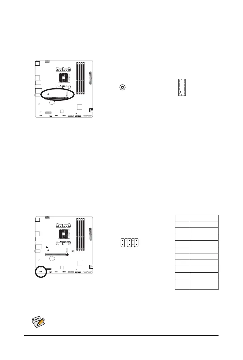
6) M2A_CPU (M.2 Socket 3 Connector)
There are two types of M.2 SSDs: M.2 SATA SSDs and M.2 PCIe SSDs. Be sure to verify which type of
M.2 SSDs is supported by the M.2 socket you want to use. Please note that an M.2 PCIe SSD cannot be
used to create a RAID set with a SATA hard drive. Please navigate to the "Conguring a RAID Set" page
of GIGABYTE's website for instructions on conguring a RAID array.
Follow the steps below to correctly install an M.2 SSD in the M.2 connector.
Step 1:
Pull the clip's tab up and out of the mounting hole. Slide the M.2 SSD into the connector at an angle.
Step 2:
Press the M.2 SSD down and then secure it by pressing the clip's tab into the mounting hole.
7) F_AUDIO (Front Panel Audio Header)
The front panel audio header supports High Denition audio (HD). You may connect your chassis front
panel audio module to this header. Make sure the wire assignments of the module connector match the
pin assignments of the motherboard header. Incorrect connection between the module connector and the
motherboard header will make the device unable to work or even damage it.
Pin No. Denition
1 MIC L
2 GND
3 MIC R
4 NC
5 Head Phone R
6 MIC Detection
7 SENSE_SEND
8 No Pin
9 Head Phone L
10
Head Phone
Detection
Some chassis provide a front panel audio module that has separated connectors on each wire
instead of a single plug. For information about connecting the front panel audio module that has
different wire assignments, please contact the chassis manufacturer.
1
2
9
10
M2A_CPU
F_USB30
F_U
B_
F_ F_
_
B
BS_
B
SB_
B
_S
S_
_
B
_U
_
B
S
123
123
123
123
1
1
1
1
BSS
S
_S
SSU
1 2 3
S3
BSSS
U
__ 3
F_USB3F
S _
S _
S _
SF
B_
B_
F
_0
S
S
_0F
_F
_
_
__B
U
S _S
_
SF_
B
USB0_B
B_
B_
F_USB3
F_USB303
_
_3U
S_
_S
SS_F
_
_
F
_SB
80
- 17 -
 Loading...