5) SATA3 0/1/2/3/4/5 (SATA 6Gb/s Connectors)
The SATA connectors conform to SATA 6Gb/s standard and are compatible with SATA 3Gb/s and SATA
1.5Gb/s standard. Each SATA connector supports a single SATA device.
Pin No. Denition
1 GND
2 TXP
3 TXN
4 GND
5 RXN
6 RXP
7 GND
To enable hot-plugging for the SATA ports, refer to Chapter 2, "BIOS Setup," "Peripherals\SATA
AndRSTConguration,"formoreinformation.
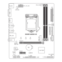
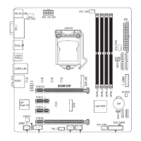
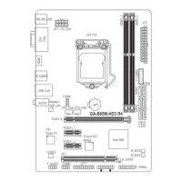
6) M2M_32G (M.2 Socket 3 Connector)
TheM.2connectorssupportM.2SATASSDsorM.2PCIeSSDsandsupportRAIDconguration.Please
note that an M.2 PCIe SSD cannot be used to create a RAID set either with an M.2 SATA SSD or a SATA
harddrive.TocreateaRAIDarraywithanM.2PCIeSSD,youmustsetupthecongurationinUEFIBIOS
mode.RefertoChapter3,"ConguringaRAIDSet,"forinstructionsonconguringaRAIDarray.
F_USB30
F_U
B_
F_ F_
_
B
BS_
B
SB_
B
_S
S_
_
B
_U
_
B
S
123
123
123
123
1
1
1
1
BSS
S
_S
SSU
1 2 3 4 5
S3
BSSS
U
__ 3
F_USB3F
S _
S _
S _
SF
B_
B_
F
_0
S
S
_0F
_F
_
_
__B
U
S _S
_
SF_
USB0_B
B_
F_USB3
_
_3U
80 60 42
Follow the steps below to correctly install an M.2 SSD in the M.2 connector.
Step 1:
LocatethepropermountingholefortheM.2SSDtobeinstalledandtheninstallthemountingcliprst.
Step 2:
Slide the M.2 SSD into the connector at an angle.
Step 3:
Press the M.2 SSD down and then secure it by pressing the clip pin into the mounting hole.
Select the proper hole for the mounting clip according to the length of the M.2 SSD to be installed.
Installation Notices for the M.2 and SATA Connectors:
Due to the limited number of lanes provided by the Chipset, the availability of the SATA connectors may be
affected by the type of device installed in the M2M_32G connector. The M2M_32G connector shares bandwidth
with the SATA3 5 connector. Refer to the following table for details.
SATA3 0 SATA3 1 SATA3 2 SATA3 3 SATA3 4 SATA3 5
M.2 SATA SSD
a a a a a
r
M.2 PCIe SSD
a a a a a a
No M.2 SSD Installed
a a a a a a
a: Available, r: Not available
Connector
Type of
M.2 SSD
SATA3
5 4
3 2
1 0
1 1
7 7
- 14 -
 Loading...