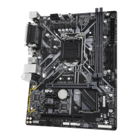
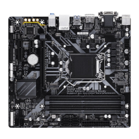
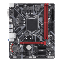
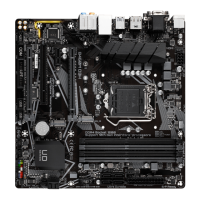
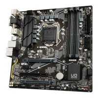
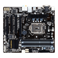
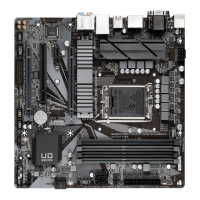
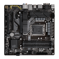
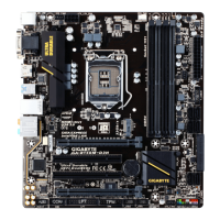
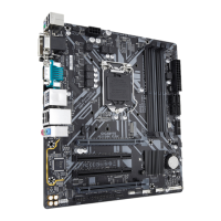
3/4) CPU_FAN/SYS_FAN1/SYS_FAN2/SYS_FAN3 (Fan Headers)
All fan headers on this motherboard are 4-pin. Most fan headers possess a foolproof insertion design.
When connecting a fan cable, be sure to connect it in the correct orientation (the black connector wire is
the ground wire). The speed control function requires the use of a fan with fan speed control design. For
optimum heat dissipation, it is recommended that a system fan be installed inside the chassis.
• Be sure to connect fan cables to the fan headers to prevent your CPU and system from
overheating. Overheating may result in damage to the CPU or the system may hang.
• Thesefanheadersarenotcongurationjumperblocks.Donotplaceajumpercapontheheaders.
SYS_FAN1
1
SYS_FAN3
1
CPU_FAN
1
SYS_FAN2
1
Pin No. Denition
1 GND
2 Voltage Speed Control
3 Sense
4 PWM Speed Control
5) LED_C (RGB LED Strip Header)
Theheadercanbeusedtoconnectastandard5050RGBLEDstrip(12V/G/R/B),withmaximumpower
rating of 2A (12V) and maximum length of 2m.
Pin No. Denition
1 12V
2 G
3 R
4 B
Before installing the devices, be sure to turn off the devices and your computer. Unplug the power
cord from the power outlet to prevent damage to the devices.
Forhowtoturnon/offthelightsoftheLEDstrip,refertotheinstructionsoninChapter2,"BIOS
Setup,""Peripherals."
1
ConnectyourRGBLEDstriptotheheader.Thepowerpin(markedwith
a triangle on the plug) of the LED strip must be connected to Pin 1 (12V)
of the LED strip header. Incorrect connection may lead to the damage of
the LED strip.
RGB
LED Strip
1
12V
- 15 -
 Loading...
