- 21 -
• Be sure to connect fan cables to the fan headers to prevent your CPU and system from
overheating. Overheating may result in damage to the CPU or the system may hang.
• These fan headers are not conguration jumper blocks. Do not place a jumper cap on the headers.
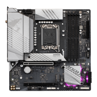
3/4) CPU_FAN/SYS_FAN1/SYS_FAN2/SYS_FAN3 (Fan Headers)
All fan headers on this motherboard are 4-pin. Most fan headers possess a foolproof insertion design.
When connecting a fan cable, be sure to connect it in the correct orientation (the black connector wire is
the ground wire). The speed control function requires the use of a fan with fan speed control design. For
optimum heat dissipation, it is recommended that a system fan be installed inside the chassis.
CPU_FAN/
SYS_FAN1
1
SYS_FAN2
1
1
Pin No. Denition
1 GND
2 Voltage Speed Control
3 Sense
4 PWM Speed Control
SYS_FAN3
Connector CPU_FAN SYS_FAN1/2/3
Maximum Current 2A 2A
Maximum Power 24W 24W
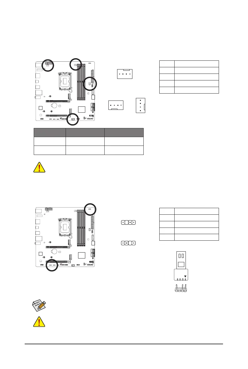
5) ARGB_V2_1/ARGB_V2_2/ARGB_V2_3 (Addressable RGB Gen2 LED Strip Headers)
The headers can be used to connect a standard 5050 addressable RGB Gen2 LED strip, with maximum
power rating of 3A (5V) and maximum number of 256 LEDs.
1
F_USB30
F_U
B_
F_ F_
_
B
BS_
B
SB_
B
_S
S_
_
B
_U
_
B
S
123
123
123
123
1
1
1
1
BSS
S
_S
SSU
1 2 3
S3
BSSS
U
__ 3
F_USB3F
S _
S _
S _
SF
B_
B_
F
_0
S
S
_0F
_F
_
_
__B
U
S _S
_
SF_
B
USB0_B
B_
B_
F_USB3
F_USB303
_
_3U
S_
_S
SS_F
_
_
F
_SB
F_
F_
ARGB_V2_1/
ARGB_V2_3
1
F_USB30
F_U
B_
F_ F_
_
B
BS_
B
SB_
B
_S
S_
_
B
_U
_
B
S
123
123
123
123
1
1
1
1
BSS
S
_S
SSU
1 2 3
S3
BSSS
U
__ 3
F_USB3F
S _
S _
S _
SF
B_
B_
F
_0
S
S
_0F
_F
_
_
__B
U
S _S
_
SF_
B
USB0_B
B_
B_
F_USB3
F_USB303
_
_3U
S_
_S
SS_F
_
_
F
_SB
F_
F_
ARGB_V2_2
For how to turn on/off the lights of the LED strip, please navigate to the "Unique Features" page
of GIGABYTE's website.
Connect your addressable RGB Gen2 LED strip to the header. The power
pin (marked with a triangle on the plug) of the LED strip must be connected
to Pin 1 of the addressable LED strip header. Incorrect connection may lead
to the damage of the LED strip.
• To avoid abnormal LED behavior, do not connect addressable RGB Gen1 LED strips and
addressable RGB Gen2 LED strips to the same header at the same time.
• Before installing or removing the devices, be sure to turn off the devices and your computer.
Unplug the power cord from the power outlet to prevent damage to the devices.
Pin No. Denition
1 V (5V)
2 Data
3 No Pin
4 GND
Addressable RGB
Gen2 LED Strip
1
 Loading...