Do you have a question about the Gigabyte GA-7PXSL and is the answer not in the manual?
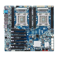
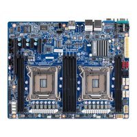
This document is the User's Manual for the GA-7PXSL motherboard, a dual LGA2011 socket motherboard designed for Intel® E5-2600 series processors. The manual provides comprehensive information on hardware installation, BIOS setup, and regulatory statements.
The GA-7PXSL motherboard is designed to support Intel® Xeon® E5-2600 V2 series processors in the LGA2011 package, with L3 cache varying by CPU. It supports QuickPath Interconnect up to 8GT/s, Enhanced Intel SpeedStep Technology (EIST), and Intel Virtualization Technology (VT). The chipset is an Intel® C602 (Patsburg-A).
For memory, the motherboard features eight 1.5V DDR3 DIMM sockets, supporting up to 64GB (UDIMM) and 256GB (RDIMM/LRDIMM) of system memory. It also supports eight 1.35V DDR3L DIMM sockets for up to 64GB of system memory. The memory architecture is four-channel, supporting 1866/1600/1033MHz memory modules and ECC RDIMM/UDIMM memory modules. The manual details four-channel memory configuration guidelines, emphasizing the use of memory modules with the same capacity, brand, speed, and chips for optimal performance. It also includes a DIMM Population Table for proper installation.
In terms of networking, the motherboard integrates dual Intel® 82574L Gigabit Network Controllers, supporting 10/100/1000 Mbps. It also includes an ASPEED® AST2300 BMC chip for management.
Expansion slots include one PCI Express x16 slot (running at x8, Gen3/PCIE16X), one PCI Express x4 slot (running at x4, Gen3/PCIE4X_1), and two PCI Express x1 slots (running at x1, Gen2/PCIE1X_2/PCIE1X_3).
Onboard graphics are provided by an ASPEED® AST2300, which supports 16MB VRAM.
Storage capabilities are managed by the Intel® C602 controller, offering two SATA 6Gb/s connectors (SATA0/SATA1), two SATA 3Gb/s connectors (SATA2/SATA3), and four SAS connectors (providing 4 additional SATA ports at 3Gb/s or option SAS ports at 3Gb/s with an upgrade key). It supports Intel RSTe SATA RAID 0/1/10/5. The manual includes an Intel C600 Upgrade ROM SKUs table, detailing SCU ports, protocol enabled, and Intel RSTe SAS RAID 5 support based on different upgrade ROM SKUs.
USB connectivity includes up to six USB 2.0/1.1 ports (two on the back panel, four via internal USB headers) and up to two USB 3.0 ports on the back panel.
Internal connectors include a 24-pin ATX main power connector, two 8-pin ATX 12V power connectors, four SAS connectors, two SATA 6Gb/s connectors, two SATA 3Gb/s connectors, a PMBus header, two CPU fan headers, four system fan headers, a front panel header, a backplane board header, two USB 2.0/1.1 headers, a TPM module connector, a serial port connector, a front audio connector, an SKU KEY header, and two SGPIO headers.
Rear panel I/O consists of two USB 2.0/1.1 ports, two USB 3.0 ports, three RJ-45 ports (one of which is a 10/100 dedicated management LAN port), one COM port, and one VGA port.
The hardware monitor features system voltage detection, CPU/system temperature detection, and CPU/system fan speed detection and control. The CPU/system fan speed control function's support depends on the installed CPU/system cooler.
The BIOS is a 1 x 64 Mbit flash with AMI BIOS. The form factor is ATX, measuring 12 inches x 9.6 inches, with an 8-layer PCB.
Usage features include detailed instructions for CPU and CPU cooler installation, emphasizing precautions such as unplugging power, avoiding contact with metal leads, using an ESD wrist strap, and applying thermal grease. Memory installation guidelines highlight the importance of compatible memory modules and proper insertion. The manual also describes the various back panel connectors and their functions, including LAN port LED states for speed and activity.
Maintenance features include jumper settings for BIOS write protection, flash descriptor security, PMBus power selection, S3 power on selection, FRB1 timer control, clearing CMOS, ME enable/disable, and supervisor password clearing. The manual provides clear instructions on how to use these jumpers for system maintenance and recovery. It also details the BIOS recovery instruction, including steps to rename the ROM file, copy it to a USB diskette, enable BIOS recovery, and proceed with a flash update. The BIOS Beep Codes section helps users diagnose system issues based on the number of beeps.
The BIOS Setup section provides a comprehensive guide to configuring system settings. It covers Main, Advanced, Chipset, Security, Server Management, Boot, and Exit menus. Key configurable items include PCI Express settings (Relaxed Ordering, Extended Tag, No Snoop, Maximum Payload, Maximum Read Request, Extended Synch, Link Training Retry, Link Training Timeout, Unpopulated Links), Runtime Error Logging, CPU Configuration (Hyper-threading, Active Processor Cores, Limit CPUID Maximum, Execute Disable Bit, Hardware Prefetcher, Adjacent Cache Line Prefetch, DCU Streamer Prefetch, DCU IP Prefetch, Intel Virtualization Technology), CPU Power Management Configuration (Power Technology, EIST, Turbo Mode, P-STATE Coordination, CPU C3/C6 Report, Package C State Limit, Energy Performance), Fan Configuration (Fan Control Policy, Fan Rise Curve), USB Configuration (Legacy USB Support, USB3.0 Support, XHCI Hand-off, EHCI Hand-off), SATA Configuration (SATA Mode Selection, Aggressive Link Power Management, Hot Plug, External SATA, SATA Device Type, Staggered Spin Up), SAS Configuration, Info Report Configuration (Post Report, Error Message Report), Super IO Configuration (Serial Port settings), Serial Port Console Redirection (Terminal Type, Bits per second, Data Bits, Parity, Stop Bits, Flow Control, VT-UTF8 Combo Key Support, Recorder Mode, Resolution, Legacy OS Redirection Resolution, Putty KeyPad, Redirection After BIOS POST, Out-of-Band Mgmt Port, SOL Switch), Network Stack, Intel (R) 82574L Gigabit Network Connection (Link Speed, Wake On LAN, Blink LEDs), Chipset Menu (IOH Configuration, QPI Configuration, Compatibility RID, Memory Configuration, DDR Speed, Channel Interleaving, Rank Interleaving, Patrol Scrub, Demand Scrub, Data Scrambling, Device Tagging, Rank Margin, Thermal Throttling, OLTT Peak BW %, Altitude, Enforce DIMM, Intel(R) VT for Directed I/O Configuration, DCA Support, VGA Priority, Gen3 Equalization WA's, IOH Resource Selection Type, No Snoop Optimization, MMCFG Size, MMCFGBASE, Intel(R) VT-d), DIMM Information, South Bridge Configuration (PCH Compatibility RID, USB WakeOnDev insertion, Restore on AC Power Loss, SCU Devices, Onboard SAS oprom, Audio Configuration, High Precision Event Timer), Intel ME Subsystem, Security Menu (Administrator Password, User Password, Secure Boot menu, Image Execution Policy, Key Management), Server Management Menu (OS Watchdog Timer, BMC LAN Configuration, Gbt BMC Function, View FRU information, System Event Log), Boot Menu (Setup Prompt Timeout, Bootup NumLock State, Quiet Boot, Fast Boot, Boot Priority Order, Network Device BBS Priorities, Hard Drive BBS Priorities, CSM16 Parameters, CSM Parameters).
The manual also includes regulatory statements, emphasizing GIGABYTE's commitment to environmental preservation through RoHS and WEEE directives, providing guidance on responsible recycling and disposal of the product.
| Brand | Gigabyte |
|---|---|
| Model | GA-7PXSL |
| Category | Motherboard |
| Language | English |