11
1
20
10
ATX
ATX:
PinNo. Denition
11 3.3V
12 -12V
13 GND
14 PS_ON (soft On/Off)
15 GND
16 GND
17 GND
18 -5V
19 +5V
20 +5V
PinNo. Denition
1 3.3V
2 3.3V
3 GND
4 +5V
5 GND
6 +5V
7 GND
8 Power Good
9 5VSB (stand by +5V)
10 +12V
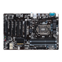
1/2) ATX_12V/ATX (2x2 12V Power Connector and 2x10 Main Power Connector)
With the use of the power connector, the power supply can supply enough stable power to all the
componentsonthe motherboard.Before connectingthe powerconnector, rstmake surethepower
supply is turned off and all devices are properly installed. The power connector possesses a foolproof
design. Connect the power supply cable to the power connector in the correct orientation. The 12V
power connector mainly supplies power to the CPU. If the 12V power connector is not connected, the
computer will not start.
ATX_12V
1
3
2
4
ATX_12V:
PinNo. Denition
1 GND
2 GND
3 +12V
4 +12V
 Loading...