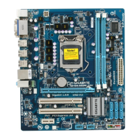
This document outlines the design and functionality of the GA-H55M-S2 motherboard, providing a comprehensive overview of its various components, interconnections, and operational characteristics. The motherboard is designed to support Intel LGA1156 processors, specifically Lynnfield/Clarkdale, and integrates a PCH (H57/H55) for managing peripheral devices and system functions.
Core Functionality:
The motherboard's core functionality revolves around the Intel LGA1156 processor, which communicates with the PCH via DMI and FDI interfaces. The PCH acts as a central hub, connecting to various subsystems including DDRIII DIMM slots (Channel A and Channel B), PCI Express slots (X16 and X1), a Realtek RTL8111E Gigabit LAN controller, USB ports, Serial ATA II ports, SPI BIOS, and an ITE8720GB-FX LPC I/O controller.
Usage Features:
- Processor Support: The GA-H55M-S2 supports Intel LGA1156 processors, offering compatibility with a range of CPUs for diverse computing needs. The CPU LGA1156-A, CPU LGA1156-B, and CPU LGA1156-C sections detail the specific pin configurations and power delivery for these processors.
- Memory Configuration: The motherboard features two DDRIII DIMM channels (Channel A and Channel B), allowing for flexible memory configurations. The DDRIII CHANNEL A and DDRIII CHANNEL B sections provide detailed schematics for memory connections, including data lines (DQ), address lines (MAAA), control signals (CKE, CS), and termination. The DDRIII POWER CAP section outlines the power decoupling for the DDR15V and DDRVTT rails, ensuring stable memory operation.
- Expansion Capabilities: The inclusion of PCI Express X16 and X1 slots provides ample expansion opportunities for graphics cards, network cards, and other high-bandwidth peripherals. The PCI EXPRESS *16 SLOT and PCI EXPRESS *1 SLOT sections detail the pinouts and signal integrity considerations for these slots. Additionally, PCI SLOT 1,2 offers compatibility with legacy PCI devices.
- Storage Options: The Serial ATA II X6 ports, managed by the PCH, provide multiple high-speed connections for hard drives and solid-state drives, supporting various storage configurations.
- Integrated Peripherals: The motherboard integrates a Realtek RTL8111E Gigabit LAN controller for high-speed network connectivity. USB PORTS 0~11 offer extensive connectivity for external devices. The AZALIA ALC888B-VD2 audio codec provides high-definition audio capabilities, with dedicated audio ports for front audio, line-out, line-in, microphone, CD-in, surround, surround back, and center/LFE channels. The REAR AUDIO JACK section details the physical connections for these audio outputs.
- I/O Connectivity: The ITE8720GB-FX LPC I/O controller manages various legacy I/O ports, including COM A, KB/PS2, and FDD, catering to a wide range of peripheral devices. The FRONT PANEL /CPU FAN section outlines connections for front panel controls and CPU cooling fans.
- BIOS and Clocking: The SPI BIOS provides essential firmware for system startup and configuration. The CLOCK GENERATOR RTM885N-914 section details the clock generation circuitry, ensuring precise timing for all system components.
- Power Management: The DISCRETE POWER section describes the various power rails and their regulation, including the ISL6545 DDR 15V, CPU VTT, PWR SEQ, CPU VAXG PWM ISL6314CRZ, and VCORE PWM ISL6333CR. These components ensure stable and efficient power delivery to the CPU, memory, and other critical parts of the motherboard. The ATX POWER, TPM section details the ATX power connector and its pin assignments, crucial for system power delivery.
Maintenance Features:
- BOM & PCB MODIFY HISTORY: This section provides a record of changes made to the Bill of Materials (BOM) and Printed Circuit Board (PCB) design, which is invaluable for tracking revisions and understanding design evolution.
- BLOCK DIAGRAM: The block diagram offers a high-level visual representation of the motherboard's architecture, illustrating the interconnections between major components. This is essential for quick troubleshooting and understanding data flow.
- Detailed Schematics: The extensive collection of schematics for each functional block (e.g., CPU LGA1156-A/B/C, DDR III CHANNEL A/B, PCH FDI/DMI/USB/PCIE/NVRAM, PCH DP/CLK BUFFER, PCH HOST/SATA/PCI, PCH GPIO/CTRL/AUDIO, PCH PWR/GND, PCI EXPRESS slots, ITE 8720 LPC IO, Dual BIOS/PHOT/D-OC, ALC888B-VD2, REAR AUDIO JACK, CLOCK GEN RTM885N-914, DISCRETE POWER, ISL6545 DDR 15V/CPU VTT/PWR SEQ, CPU VAXG PWM ISL6314CRZ, VCORE PWM ISL6333CR, F PANEL/F USB/FDD, ATX POWER/TPM, REALTEK RTL8111E, HWM/KB/MS/FAN CTRL) provides granular detail for diagnostic purposes. These schematics include pinouts, component values, and signal names, enabling engineers to trace signals and identify potential issues.
- Power-On Strapping Options: The ITE8720 Power on Strapping section details various configuration options, such as enabling/disabling VID/SVID output pins, SPI-Flash, k8 power sequencing, WDT reset PWROK, parallel/serial VID output, and Dual BIOS function. These options are crucial for customizing the motherboard's behavior and troubleshooting power-related issues.
- DMI Terminator Voltage: The DMI Terminator voltage settings (HI: AC COUP: TX/RX TO VCC, LO: DC COUP: HALF SWING) provide flexibility for optimizing DMI signal integrity, which can be important for system stability and performance.
- USB OC# Configure: The USB OC# Configure table allows for specific settings for USB overcurrent protection, enabling granular control over USB port behavior and troubleshooting.
- BIOS Super I/O IT8720 GPIO Table: This table provides a comprehensive list of GPIO pins and their functions, which is essential for understanding the interaction between the BIOS and the Super I/O chip, and for debugging control signals.
- PWM Control: The PWM control section details the various PWM signals for CPU, DDR, and VCORE, including their corresponding ISL controllers. This information is critical for diagnosing power delivery issues and ensuring proper voltage regulation.
- HWM, KB/MS, FAN CTRL: This section provides details on hardware monitoring, keyboard/mouse interfaces, and fan control, which are important for system health monitoring and thermal management.
- TABLE LIST: The table list provides a quick reference to all the tables within the document, facilitating navigation and information retrieval.