GA-MA69VM-S2 Motherboard - 18 -
English
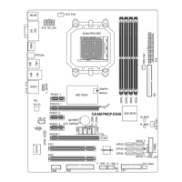
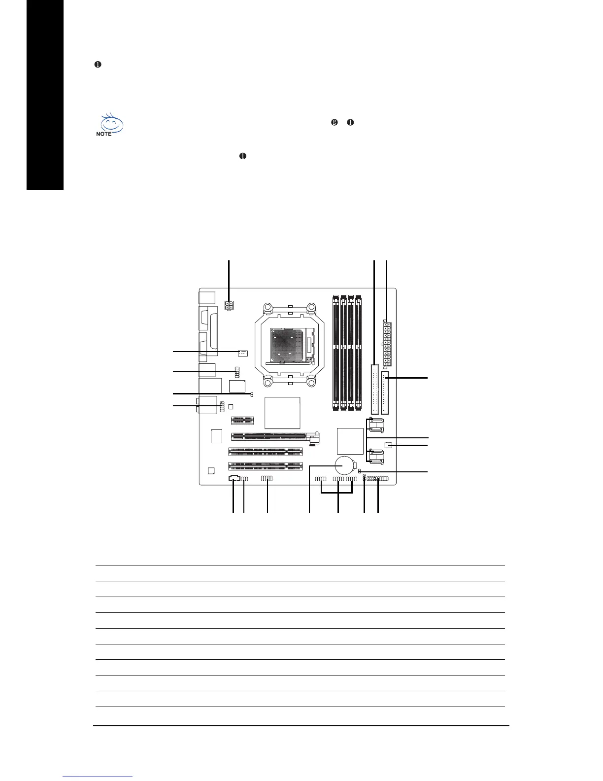
1-7 Connectors Introduction
In addition to the default speakers settings, the ~ audio jacks can be reconfigured to
perform different functions via the audio software. Only microphones still MUST be connected
to the default Mic In jack ( ). Please refer to the 2-/4-/6-/8- channel audio setup steps for
detailed software configuration information.
MIC In
The default MIC In jack. Microphone must be connected to MIC In jack.
1) ATX_12V
2) ATX (Power Connector)
3) CPU_FAN
4) SYS_FAN
5) FDD
6) IDE
7) SATAII0 /1 /2 /3
8) F_PANEL
9) CD_IN
10) F_AUDIO
11) F_USB1 / F_USB2/ F_USB3
12) POWER_LED
13) CI
14) CLR_CMOS
15) BATTERY
16) TV
17) SPDIF_IO
18) COMB
12
3
5
4
7
89 11
13
15 12
16
17
18
10
14
6
 Loading...