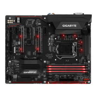
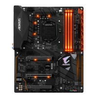
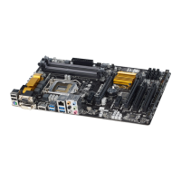
6) SATA3 0/1/2/3/4/5 (SATA 6Gb/s Connectors)
The SATA connectors conform to SATA 6Gb/s standard and are compatible with SATA 3Gb/s and SATA
1.5Gb/s standard. Each SATA connector supports a single SATA device. The Intel
®
ChipsetsupportsRAID0,
RAID1,RAID5,andRAID10.RefertoChapter3,"ConguringaRAIDSet,"forinstructionsonconguring
aRAIDarray.
Pin No. Denition
1 GND
2 TXP
3 TXN
4 GND
5 RXN
6 RXP
7 GND
Toenablehot-pluggingfortheSATAports,refertoChapter2,"BIOSSetup,""Peripherals\SATA
AndRSTConguration,"formoreinformation.
1
5) SYS_FAN3_PUMP (System Fan/Water Cooling Pump Header)
The pump header is 4-pin and possesses a foolproof insertion design. Most fan headers possess a foolproof
insertion design. When connecting a fan cable, be sure to connect it in the correct orientation (the black
connector wire is the ground wire). The speed control function requires the use of a fan with fan speed control
design. For optimum heat dissipation, it is recommended that a system fan be installed inside the chassis.
Theheaderalsoprovidesspeedcontrolforawatercoolingpump,refertoChapter2,"BIOSSetup,""M.I.T.,"
for more information
Pin No. Denition
1 GND
2 Voltage Speed Control
3 Sense
4 PWM Speed Control
SATA3
1 0
3 2
SATA3
77
11
1
1
7
7
5
4
7) M2P_32G (M.2 Socket 3 Connector)
TheM.2connectorsupportsM.2SATASSDsandM.2PCIeSSDsandsupportRAIDcongurationthrough
the Intel
®
Chipset. PleasenotethatanM.2PCIeSSDcannotbeusedtocreateaRAIDseteitherwith
anM.2SATASSDoraSATAharddriveandcanonlybeusedtobuildaRAIDsetwithUEFI.Refer
toChapter3,"ConguringaRAIDSet,"forinstructionsonconguringaRAIDarray.
Follow the steps below to correctly install an M.2 SSD in the M.2 connector.
Step 1:
Use a screw driver to unfasten the screw and nut from the motherboard. Locate the proper mounting hole for
theM.2SSDtobeinstalledandthenscrewthenutrst.
Step 2:
Slide the M.2 SSD into the connector at an angle.
Step 3:
Press the M.2 SSD down and then secure it with the screw.
Select the proper hole for the M.2 SSD to be installed and refasten the screw and nut.
F_USB30
F_U
B_
F_ F_
_
B
BS_
B
SB_
B
_S
S_
_
B
_U
_
B
S
123
123
123
123
1
1
1
1
BSS
S
_S
SSU
1 2 3
S3
BSSS
U
__ 3
F_USB3F
S _
S _
S _
SF
B_
B_
F
_0
S
S
_0F
_F
_
_
__B
U
S _S
_
USB0_B
B_
80 60 42
- 14 -
 Loading...