- 12 -
Hardware Installation
Socket
Socket
Security
Security
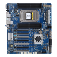
Expansion Slot Riser Card CRS101E:
1 x PCIe x16 slot (Gen4 x16), Full-height half-length
Riser Card CRS101G:
1 x PCIe x16 slot (Gen4 x16), Full-height half-length
1 x OCP 3.0 mezzanine slot with PCIe Gen4 x16 bandwidth from CPU_0
Supported NCSI function
1 x OCP 2.0 mezzanine slot with PCIe Gen3 x8 bandwidth from CPU_1
Supported NCSI function
Socket
Socket
Security
Security
Internal I/O 2 x SATA 7-pin connectors
2 x CPU fan headers
1 x USB 3.0 header
1 x TPM header
1 x VROC connector
1 x Front panel header
1 x HDD back plane board header
1 x IPMB connector
1 x Clear CMOS jumper
1 x BIOS recovery switch
Socket
Socket
Security
Security
Front I/O 2 x USB 3.0
1 x Power button with LED
1 x ID button with LED
1 x Reset button
1 x NMI button
1 x HDD activity LED
1 x System status LED
Socket
Socket
Security
Security
Rear I/O
2 x USB 3.0
1 x VGA
1 x MLAN
1 x ID button with LED
Socket
Socket
Security
Security
Backplane I/O
Backplane PN: 9CBP1047NR-00
4 x 3.5" or 2.5" SATA/SAS ports
Bandwidth: SATA 6Gb/s, SAS 12Gb/s per port or PCIe Gen4 x4
Socket
Socket
Security
Security
TPM 1 x TPM header with SPI interface
Optional TPM2.0 kit: CTM010
 Loading...