5) LED_C(RGBLEDStripHeader)
Theheadercanbeusedtoconnectastandard5050RGBLEDstrip(12V/G/R/B),withmaximumpower
ratingof2A(12V)andmaximumlengthof2m.
Pin No. Denition
1 12V
2 G
3 R
4 B
Before installing the devices, be sure to turn off the devices and your computer. Unplug the power
cord from the power outlet to prevent damage to the devices.
ConnectyourRGBLEDstriptotheheader.Thepowerpin(marked
withatriangleontheplug)oftheLEDstripmustbeconnectedtoPin
1(12V)ofthisheader.Incorrectconnectionmayleadtothedamage
oftheLEDstrip.
RGBLEDStrip
1
12V
1
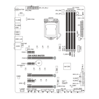
6) SATA30/1/2/3/4/5(SATA6Gb/sConnectors)
The SATA connectors conform to SATA 6Gb/s standard and are compatible with SATA 3Gb/s and SATA
1.5Gb/s standard. Each SATA connector supports a single SATA device. The Intel
®
ChipsetsupportsRAID0,
RAID1,RAID5,andRAID10.RefertoChapter3,"ConguringaRAIDSet,"forinstructionsonconguring
aRAIDarray.
Pin No. Denition
1 GND
2 TXP
3 TXN
4 GND
5 RXN
6 RXP
7 GND
Toenablehot-pluggingfortheSATAports,refertoChapter2,"BIOSSetup,""Peripherals\SATA
AndRSTConguration,"formoreinformation.
Forhowtoturnon/offthelightsoftheLEDstrippleasevisitthe"UniqueFeatures"webpageof
GIGABYTE's website.
SATA3
SATA3
3 2
1 0
5
4
7
1
7
1
17
17
- 15 -

 Loading...