Do you have a question about the Gira System 106 and is the answer not in the manual?
Key considerations for installation height and maximum cable length to ensure proper function.
Marking drill holes, preparing cable entry points, and ensuring seal integrity.
Firmly insert wall plugs and install modules into the function carrier, ensuring correct orientation.
Attach terminating resistors and system cables, ensuring correct placement on the bus.
Trim and connect the connection cable to the plug terminal, and attach to the module connector.
Guidelines on connecting BUS and ZV, and automatic detection of additional power supply.
Secure the safety bond (120 mm) to the housing for added safety.
Swivel function carriers into surface-mounted housings, paying attention to cable position and snap locks.
Use the provided bit holder and bit to close the housing, checking gap sizes for tightness.
| Speakerphone | Yes |
|---|---|
| Connector type | 10 pole connector |
| Buttons quantity | 1 |
| Modules quantity (max) | 1 module(s) |
| Connectivity technology | Wired |
| Power over Ethernet (PoE) | No |
| International Protection (IP) code | IP54 |
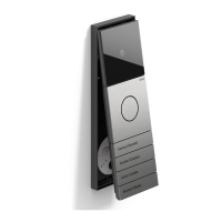
| Product color | Stainless steel |
| Operating temperature (T-T) | -25 - 70 °C |
| Outdoor unit power type | AC/DC |
| Width | 106.5 mm |
|---|