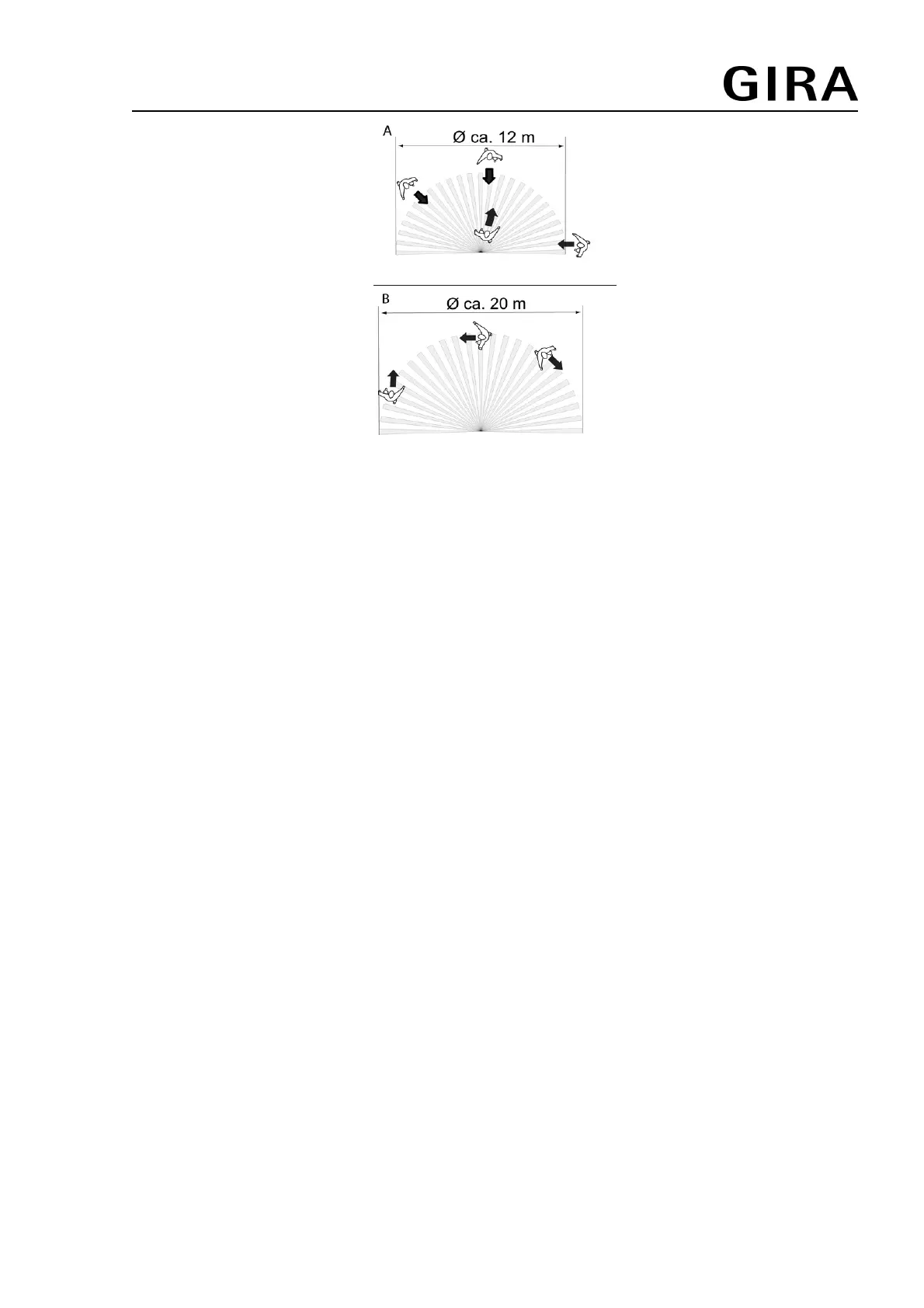
Figure 3: Detection area dependent on the direction of movement
i Note direction of motion (Figure 3). Motions that are transverse to the motion detector
(Drawing B) can be detected better than motions towards or away from the motion detector
(Drawing A).
o Select a vibration-free installation location. Vibrations can lead to unwanted switching.
o Avoid interference sources in the detection area. Interference sources, e.g. heaters,
ventilation, air conditioners, and cooling light bulbs can lead to unwanted switching.
i If necessary, the detection area can be limited using the push-on top (see Limiting the
detection area).
i At an installation height of greater than 3 m the detection area increases, while at the same
time the detection sensitivity decreases.
Installing the motion detector cover
o Align the motion detector so that the brightness sensor is on the side away from the
windows. This reduces the effects of scattered light.
o Connect flush-mounted insert properly and mount in accordance with the orientation of the
motion detector (see instructions for flush-mounted insert).
i Use a surface-mounted housing for surface installation.
i Use a wind-tight connector socket for cavity wall mounting.
o Attach the motion detector cover to the flush-mounted insert.
Expanding the detection area
To expand the detection area, connect a 3-wire extension insert with motion detector cover. The
motion detector of the main unit also evaluates motion signals of the extension and, if
necessary, switches the lighting on.
o Connect extensions (see instructions for 3-wire extension insert).
i The sensitivity of motion detectors on extensions can be set individually. The brightness
threshold and run-on time are only set and evaluated on the main device.
i Do not connect any main units in parallel.
82563812 18.11.2011
4/8
System 2000
System 2000 automatic control switch 360°
 Loading...