3/4
F – REMPLACEMENT DU TUYAU :
ATTENTION: AVANT D'EFFECTUER TOUTE OPERATION :
1. POSITIONNER LA BUTEE D'ARRET A L'EXTREMITE DU TUYAU,
2. ENROULER COMPLETEMENT LE TUYAU
3. S'ASSURER QUE LE RESSORT EST TOTALEMENT DETENDU.
Pour des raisons de sécurité, les opérations de remplacement du tuyau doivent être effectuées sur établi.
Utiliser un tuyau ayant des caractéristiques de dimensions et de pression adaptées à l'emploi
(voir tableau des caractéristiques
techniques)
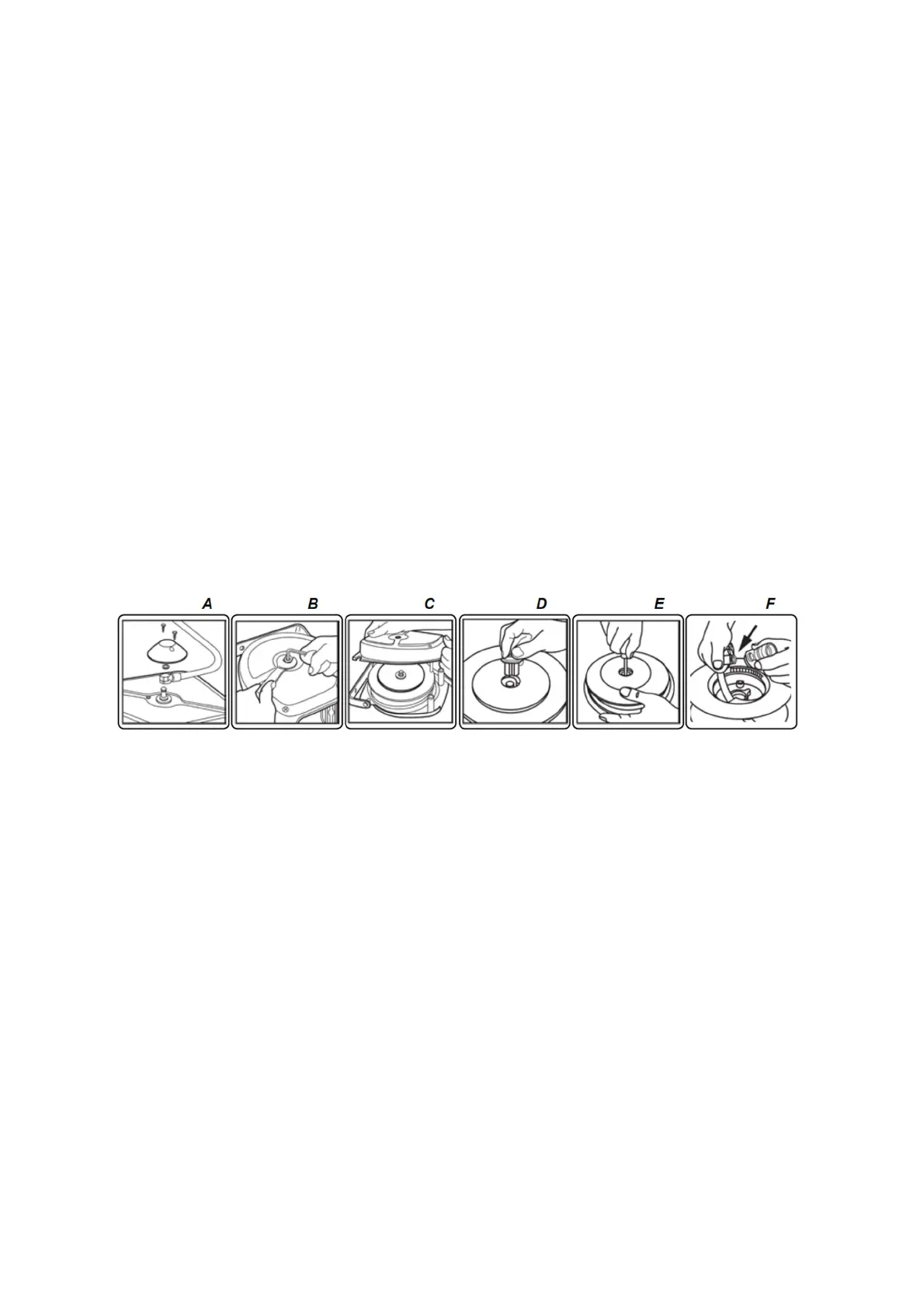
1) Démonter le tuyau d'alimentation en enlevant le couvercle en plastique et le circlip (figure A).
2) Insérer une clé hexagonale de 5 dans les 6 pans du moyeu du ressort. Dévisser l'écrou avec une clé de 19 en retenant avec la clé
hexagonale (figure B). Décharger le ressort en tournant lentement la clé hexagonale dans le sens des aiguilles d'une montre.
3) Enlever l'écrou et les 4 vis de fixation des 2 demi-carters.
4) Enlever le demi-carter et le guide tuyau et extraire le tambour (figure C).
ATTENTION: NE PAS OUVRIR LE CARTER DU RESSORT. LES OPERATIONS DE REPARATION OU DE REMPLACEMENT DU
RESSORT NE DOIVENT ETRE EFFECTUEES QUE PAR DES TECHNICIENS HABILITES.
5) Extraire le moyeu ressort du tambour (figure D).
6) Dévisser la vis centrale et enlever la douille (figure E).
7) Séparer le moyeu du tambour et extraire le raccord du tuyau du moyeu (figure F). Enlever le joint O-RING.
8) Couper le collier afin de récupérer le raccord et remplacer le tuyau.
9) Mettre l'O-RING sur le raccord et insérer le raccord dans le trou du tuyau.
10) Monter de nouveau le moyeu dans le tambour en serrant la vis centrale et insérer le moyeu du ressort.
11) Monter la butée de fin de course à environ 1 m de l’extrémité et enrouler le tuyau sur le tambour.
12) Graisser éventuellement. Monter de nouveau l’enrouleur suivant les opérations inverses.
13) Insérer une clé hexagonale dans le trou du moyeu. Tourner la clé dans le sens inverse des aiguilles d’une montre de sorte que la
butée de fin de course soit en contact avec le guide tuyau.
Précontraindre le ressort en continuant à tourner la clé de 3 tours dans le sens inverse des aiguilles d’une montre.
14) Retenir la clé et bloquer l’écrou. Vérifier le bon fonctionnement. Si le tuyau ne rentre ou ne sort pas complètement, réajuster la
tension du ressort (point 13).
15) Monter de nouveau le tuyau d’alimentation et le couvercle en plastique
GB – HOSE REPLACEMENT
WARNING : BEFORE PERFORMING ANY OPERATION :
1. POSITION THE STOPPER AT THE END OF THE HOSE,
2. REEL THE HOSE COMPLETELY ,
3. MAKE SURE THAT THE SPRING IS COMPLETELY SLACKENED
For safety reasons, operations of hose replacement must be carried out at the bench.
Use a hose with dimension and pressure characteristics suited to the use (see table of characteristics).
1) Take the inlet hose off by removing the plastic cap and the seeger (figure A).
2) Insert a 5 mm hexagon driver into the 6 flats of the spring hub. Unfasten the nut with a
19 mm driver, holding in place with the hexagon driver (figure B). Release the spring by turning the hexagon driver slowly clockwise.
3) Remove the nut and the 4 attachment screws from the two half-casings.
4) Remove the half-casing and take out the drum (figure C).
WARNING : DO NOT OPEN THE SPRING CASING. SPRING REPAIR OR REPLACEMENT OPE- RATIONS MUST ONLY BE
PERFORMED BY QUALIFIED TECHNICIANS.
5) Take the spring hub out of the drum (figure D).
6) Unfasten the central screw and remove the bushing (figure E).
7) Separate the hub from the drum and take the tube coupling out of the hub
(figure F). Remove the o-ring.
8) Cut the collar in order to retrieve the coupling and replace the tube.
9) Position the o-ring on the coupling and insert the coupling into the hub hole.
10) Reposition the hub in the drum by fastening the central screw and insert the spring hub.
11) Fit the stop approximately 1 m from the opposite end of the hose and reel the new hose on the drum.
12) Grease if required. Reassemble the reel, following the operations in reverse order.
13) Insert a hexagonal wrench in the hub hole. Turn the wrench anti-clockwise so that the Iimit stop is in contact with the hose guide
end fitting. Prestress the spring by continuing to turn the wrench anti-clockwise (4 turns).
14) Hold the wrench in position and fasten the nut. Perform a functional check. If the hose does not go in completely or does not come
out completely, readjust the tension of the spring (point 13).
15) Reposition the inlet hose and the plastic cap
 Loading...