4
Tools and Parts
Gather the required tools and parts before starting installation.
Tools Supplied
■ 10 mm wrench ■ 5 mm
Allen
®†
Wrench
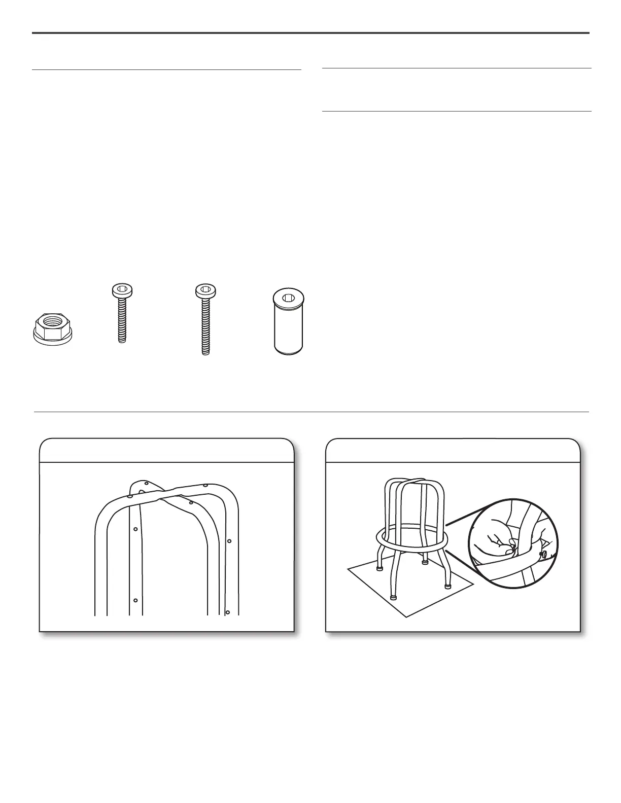
Parts Supplied
ASSEMBLY INSTRUCTIONS
Stool Use Requirements
Intended for use in a garage.
Unpack the Stool
1. Unpack the legs, seat and parts from the box. Verify contents.
See “Parts Supplied.”
2. Remove the cardboard packing and set aside for use during
assembly. After completion of assembly, dispose of all
packaging materials properly.
NOTE: Place the cardboard packing on a level oor and use
during assembly to protect the stool from scratches.
■ Upper leg frame
■ Lower leg frame
■ Smaller ring
■ Larger ring
■ Swivel plate
■ Seat
■ M6 - 1.00 x 14 Pan-head Allen
screw (8)
■ M6 - 1.00 x 20 Pan-head Allen
screw (4)
■ M6 - 1.00 x 30 Pan-head Allen
screw (4)
■ M6 - 1.00 Sleeved Allen nut (8)
■ M6 - 1.00 Flanged nut (4)
M6 - 1.00 x 14
Pan-head
Allen screw (8)
M6 - 1.00 x 28
Pan-head
Allen screw (8)
M6 - 1.00
Sleeved Allen
nut (8)
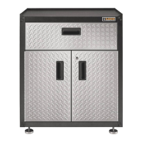
1. Stand up leg assemblies
Assemble Legs and Seat
Stand the lower leg frame upright with the center at section
facing upward. Place the upper leg frame, with the center at
section facing down, over the top of the lower leg frame as
shown.
2. Attach larger ring
Keeping the leg assembly upright, position the larger ring
over the top of leg frame and move down to align with the
lower holes in the sides of the legs. Insert four M6 - 1.00 x 14
Pan-head Allen screws through the larger ring then through
the leg. Insert four M6 - 1.00 Sleeved Allen nuts and nger
tighten.
M6 - 1.00
Flanged
Nut (4)
†®
Allen is a registered trademark of Apex Brands, Inc.