EasyManua.ls Logo

GLI International P33 User Manual

GLI International P33
91 pages
To Next Page IconTo Next Page
Page #1 background imageLoading...
Page #1 background image
Rev. 6-1100 Model P33 pH/ORP Analyzer (panel-mount 1/4 DIN)
1
OPERATING INSTRUCTION MANUAL
Model P33
pH/ORP Analyzer
(Panel-mount 1/4 DIN style;
selectable for pH or ORP measurement)
Worldwide Headquarters and Sales:
GLI International, Inc.
9020 West Dean Road
Milwaukee, Wisconsin 53224
U.S.A.
Represented By:
In the interest of improving and updating its equipment, GLI reserves the right to alter specifications to equipment at any time.
A company
Viridor Instrumentation
Phone:
Fax:
E-mail:
Web:
[414] 355-3601
[414] 355-8346
info@gliint.com
www.gliint.com
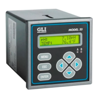
Table of Contents

Questions and Answers:

GLI International P33 Specifications

General IconGeneral
BrandGLI International
ModelP33
CategoryMeasuring Instruments
LanguageEnglish

Summary

IMPORTANT SAFETY INFORMATION

CONDENSED OPERATING INSTRUCTIONS

CONNECTING SENSOR/CONFIGURING SENSOR TYPE AND TEMPERATURE ELEMENT

Details connecting sensors and setting up temperature elements for measurement.

CONNECTING LINE POWER

Instructions for safely connecting the analyzer to a power source.

CONFIGURING BUFFER TYPE/CALIBRATING THE ANALYZER

Guides on selecting buffer types and performing initial analyzer calibration.

COMPLETING ANALYZER CONFIGURATION

Steps for finalizing analyzer setup based on application requirements.

PART TWO - INSTALLATION

SECTION 3 - ELECTRICAL CONNECTIONS

GLI 5-Wire Differential Technique Sensor

Instructions for connecting GLI sensors with built-in temperature elements.

Conventional Combination Electrode

Guidelines for connecting standard pH/ORP electrodes.

Analog Outputs

Details how to connect the analyzer's isolated analog outputs.

Relay Outputs

Explains how to connect the analyzer's electromechanical relay outputs.

Line Power

Guides on connecting the analyzer to various AC power sources.

PART THREE - OPERATION

SECTION 3 - ANALYZER CONFIGURATION

Configuring Sensor Characteristics

Details on setting up sensor type, calibration buffers, and temperature elements.

SELECT BUFFER Set for pH Calibration

Guides on selecting buffer sets for accurate pH calibration.

Select TEMP ELEMENT Type

Configures the analyzer for automatic or manual temperature compensation.

Configuring Analog Outputs (1 and 2)

Guides on assigning parameters and setting output ranges for analog signals.

Configuring Relays (A and B)

Guides on assigning parameters and modes for relay outputs.

SET FUNCTION Mode (alarm, control or status)

Selects the operational mode for each relay (ALARM, CONTROL, STATUS).

ACTIVATION (configuration values)

Describes specific settings for ALARM and CONTROL relay modes.

SET PASSCODE (feature enabled/disabled)

How to enable or disable passcode protection for settings and calibration.

Configuration Setting Summary

Provides a comprehensive list of all settings, ranges, and factory defaults.

SECTION 4 - ANALYZER CALIBRATION

Important Information

Covers general calibration notes, aborting procedures, and calibration frequency.

pH Calibration

Details the methods for calibrating the analyzer for pH measurements.

2 POINT BUFFER Method

Describes the recommended two-buffer calibration procedure.

1 POINT BUFFER Method

Explains the single-buffer calibration method for pH.

2 POINT SAMPLE Method

Details the two-sample calibration method for pH.

1 POINT SAMPLE Method

Explains the single-sample calibration method for pH.

ORP Calibration

Guides on calibrating the analyzer for ORP measurements using the 1-point method.

Analog Outputs (1 and 2) Calibration

Details how to recalibrate the analyzer's analog output signals.

SECTION 5 - TEST/MAINTENANCE

STATUS Checking (analyzer, sensor, and relays)

How to check the operational status of the analyzer, sensor, and relays.

SECTION 6 - RELAY OVERFEED TIMER FEATURE

SECTION 7 - HART OPTION

Analyzer Operating Modes for HART Network

Explains SINGLE and MULTI-DROP modes for HART communication.

SINGLE MODE (Point-to-Point) Wiring Arrangement

Describes wiring for HART communication in a single analyzer setup.

MULTI-DROP Wiring Arrangement

Describes wiring for HART communication with multiple analyzers.

HART Preferences Setup

Guides on configuring HART network preferences.

Device Preferences Setup

How to set up analyzer device-specific information and preferences.

PART FOUR - SERVICE AND MAINTENANCE

SECTION 2 - PRESERVING MEASUREMENT ACCURACY

SECTION 3 - TROUBLESHOOTING

Ground Loops

Explains ground loops, their causes, and how to detect them.

Isolating Measuring System Problem

Guides on troubleshooting by checking connections, sensor, and analyzer operation.

Verifying Analyzer Operation

How to simulate inputs to test the analyzer's functionality.

SECTION 4 ANALYZER REPAIR/RETURN

Related product manuals