Do you have a question about the GLI P63 and is the answer not in the manual?
Steps for connecting the pH sensor and configuring the analyzer for sensor type.
Procedure for adjusting the display contrast for optimal visibility.
Guide to calibrating the analyzer using different methods, recommended for first-time use.
Steps for configuring analyzer features like outputs, alarms, and PID controller.
Details the analyzer's key features, including sensor input, display, diagnostics, and output options.
Explains the analyzer's construction for serviceability and electrical safety.
Describes how configuration values are stored indefinitely without battery backup.
Provides information on locating the analyzer's serial number.
Discusses the analyzer's protection against electromagnetic and radio frequency interference.
Lists operational specifications like display, ranges, and input/output capabilities.
Details electrical performance, accuracy, sensitivity, and output specifications.
Covers enclosure type, mounting configurations, and net weight.
Instructions for unpacking, checking for shipping damage, and retaining materials.
Recommendations for placing the analyzer near the sensor and within environmental limits.
Instructions and diagrams for panel, wall, horizontal, and vertical pipe mounting.
Guidelines for using conduits for wiring to maintain enclosure integrity.
Detailed instructions for connecting GLI Differential Technique pH sensors.
Procedures for connecting conventional combination pH electrodes.
Guidance for connecting other types of pH electrodes, referring to customer service.
Information on using TTL inputs for wash/cal systems.
Configuration of 4-20 mA and 0-5 VDC/0-1 mA analog outputs for pH or temperature.
Wiring details for electromechanical, solid state AC, and solid state DC relays.
How to connect TTL outputs for NAMUR diagnostics or wash/cal systems.
Instructions for connecting the analyzer to AC line power safely.
Description of the liquid crystal display and its information presentation.
Explanation of each key's function and navigation within menus.
How to navigate, select, and confirm entries for configuration parameters.
Overview of the analyzer's menu tree and navigation symbols.
Procedure for adjusting the display contrast for optimal visibility.
Guidance on performing the initial sensor calibration before first use.
Recommendations for initial analyzer configuration based on application needs.
Diagram and explanation of the CALIBRATE menu and its submenus.
Essential information about pH calibration, including intervals and temperature correction.
How the analyzer prompts for and handles first-time sensor calibration.
Details four methods for pH calibration: Arbitrary, Pre-Defined, Sample, and Wash/Cal.
When and how to perform temperature calibration for high accuracy needs.
Overview of the CONFIGURE menu, its options, and handling of non-equipped features.
Setup and tuning for the optional PID controller, including tuning, mode, and timers.
Configuration of relays and TTL outputs for control, alarm, or NAMUR diagnostics.
Setup and scheduling for automatic wash and calibration cycles.
Choosing the temperature compensation method for accurate pH readings.
Configuring the first analog output for pH, temperature, or PID controller status.
Configuring the second analog output, including an ALARM mode option.
Setting sensor type, pulse suppression, calibration buffer values, and stability mode.
Defining output states (relays, TTL, analog) for calibration or maintenance procedures.
Configuring software alarms for various parameters and their associated TTL outputs.
Adjusting the display resolution for the main MEASURE screen.
Setting the analyzer's internal real-time clock for accurate event logging.
Enabling and setting a passcode to restrict access to analyzer menus.
Guidance on inspecting sensor cables for physical damage and continuity.
Step-by-step instructions for safely removing and reattaching the analyzer door.
Detailed procedures for replacing defective relays on the power supply board.
Instructions for safely replacing fuses in the analyzer.
Importance of periodic sensor cleaning for maintaining measurement accuracy.
Recommendations for periodic recalibration to ensure ongoing measurement accuracy.
Tips on preventing electrical noise and interference from affecting sensor signals.
Explains ground loop problems, common causes, symptoms, and a testing method.
Steps to isolate problems within the sensor, analyzer, or interconnect cable.
Contact information and procedures for obtaining troubleshooting or repair assistance.
List of available spare parts, kits, and assemblies with their part numbers.
| Brand | GLI |
|---|---|
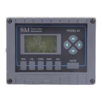
| Model | P63 |
| Category | Measuring Instruments |
| Language | English |